7/03
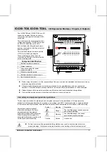
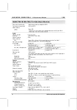
IO-DI8-TO8, IO-DI8-TO8-L
I / O E x p a n s i o n M o d u l e s
Unitronics Industrial Automation
7
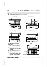
Notes:
1.
The inputs' LEDs light up only when communication link is established between module and OPLC.
2.
Input #7 can function either as a high-speed counter, a frequency measurer, or as a normal digital input.
When Input #7 is used as a normal digital input, normal input specifications apply.
3.
Input #6 can function either as the counter’s reset, or as a normal digital input; in either case, its
specifications are those of a normal digital input.
4.
When an output is connected to a load that short-circuits, that output turns off and the S.C. LED lights up on
the module. The short circuit is also identified by the software program within the controller connected to the
module. Within the M90 OPLC, for example, SB 5 turns ON. SI 5 contains a bitmap indicating the module
containing the affected output. For more information, refer to the on-line help supplied with the controller.
Addressing I/Os on Expansion Modules
Inputs and outputs located on I/O expansion modules that are connected to an OPLC are assigned addresses that
comprise a letter and a number. The letter indicates whether the I/O is an input (I) or an output (O). The number
indicates the I/O’s location in the system. This number relates to both the position of the expansion module in the
system, and to the position of the I/O on that module.
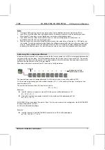
Expansion modules are numbered from 0-7 as shown in the figure below.
0
1
2
3
4
5
6
7
Expansion module
identification number
Adapter
The formula below is used to assign addresses for I/O modules used in conjunction with the OPLC.
X is the number representing a specific module’s location (0-7). Y is the number of the input or output on that
specific module (0-15).
The number that represents the I/O’s location is equal to:
32 + x • 16 + y
Examples
Input #3, located on expansion module #2 in the system, will be addressed as I 67,
67 = 32 + 2 • 16 + 3
Output #4, located on expansion module #3 in the system, will be addressed as O 84,
84 = 32 + 3 • 16 + 4.
EX90-DI8-RO8 is a stand-alone I/O module. Even if it is the only module in the configuration, the EX90-DI8-RO8
is always assigned the number 7.
Its I/Os are addressed accordingly.
Example
Input #5, located on an EX90-DI8-RO8 connected to an OPLC will be addressed
as I 149, 149 = 32 + 7 • 16 + 5


