background image

1 1 / 0 0  

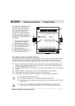
IO-DI16    

I / O   E x p a n s i o n   M o d u l e


Unitronics Industrial Automation Systems  

 3 


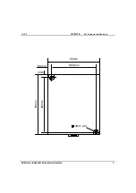
4mm

5.8mm

85mm

80mm

68.4mm

93mm

4mm (x2)


Summary of Contents for IO-DI16

Page 1: ...hnician or engineer trained in the local and national electrical standards should perform tasks associated with the electrical wiring of this device Under no circumstances will Unitronics be liable or responsible for any consequential damage that may arise as a result of installation or use of this equipment and is not responsible for problems resulting from improper or irresponsible use of this d...

Page 2: ...om edges of the device and the enclosure walls Do not place in water or let water leak onto the unit Do not allow debris to fall inside the unit during installation DIN rail mounting Snap the device onto the DIN rail as shown below the module will be squarely situated on the DIN rail 60mm 3 5mm 14mm 80mm 93mm 44 5mm IO DI16 9 8 10 11 12 13 14 15 I7 I6 I5 I4 I3 I2 I1 I0 I8 I9 I10 I11 I12 I13 I14 I1...

Page 3: ...11 00 IO DI16 I O Expansion Module Unitronics Industrial Automation Systems 3 4mm 5 8mm 85mm 80mm 68 4mm 93mm 4mm x2 ...

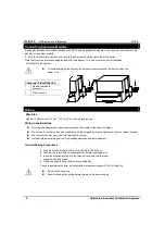
Page 4: ... AWG wire 0 13 mm 2 3 31 mm2 for all wiring purposes Wiring Considerations Note that the adapter and input signals must be connected to the same 0V signal Do not use tin solder or any other substance on the stripped wire that might cause the wire strand to break We recommend that you use crimp terminals for wiring Install at maximum distance from high voltage cables and power equipment General Wir...

Page 5: ...inputs may be wired as either pnp or npn inputs npn sink input wiring shown in top group of inputs high speed counter frequency measurer npn sink I8 I9 I10 I11 I12 I13 I14 I15 P N 0V 0V V Circuit Protection Device High speed Counter Reset High speed Counter pnp source IO DI16 9 8 10 11 12 13 14 15 I7 I6 I5 I4 I3 I2 I1 I0 I8 I9 I10 I11 I12 I13 I14 I15 P N 0V P N 0V 0V V Circuit Protection Device 0V...

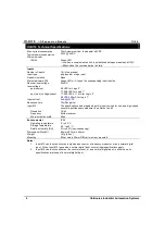
Page 6: ...gic 0 0 5VDC 4 3mA for Logic 1 Input current 6mA 24VDC Response time 10mSec typical Input 15 The specifications below apply when this input is wired for use as a high speed counter input frequency measurer See Notes 1 and 2 Resolution 16 bit Frequency 5kHz maximum Minimum pulse width 80µs Environmental IP20 Operating temperature 0 to 50 C Storage temperature 20 to 60 C Relative Humidity RH 5 to 95...

Page 7: ...dule identification number Adapter The formula below is used to assign addresses for I O modules used in conjunction with the M90 OPLC X is the number representing a specific module s location 0 7 Y is the number of the input or output on that specific module 0 15 The number that represents the I O s location is equal to 32 x 16 y Examples Input 3 located on expansion module 2 in the system will b...

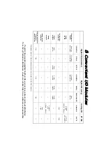
Page 8: ...conjunction with the EX A1 adapter 12 bit sign 2 outputs 10V 0 20mA 4 20mA 12 bit 4 inputs 0 10V 0 20mA 4 20mA IO AI4 AO2 Analog I O To order the expansion module that best fits your system contact your local distributor For a list of Unitronics distributors check our website http www unitronic com contact htm 12 bit 4 PT100 50 to 460 C IO PT4 PT 100 8 8 8 8 8 8 8 8 C C C C C C C C o o o o o o o o...

Reviews: