


12/03
IO-ATC8
I / O E x p a n s i o n M o d u l e
IO-ATC8 Technical Specifications
Max. current consumption
40mA maximum from the adapter’s 5VDC
Typical power consumption
0.2W@5VDC
Status indicator
(RUN) Green
LED:
—Lit when a communication link is established between module and OPLC.
—Blinks when the communication link fails.
Thermocouple Inputs
Number of inputs
8. See Note 1.
Input type
Thermocouple, differential inputs. See Note 2.
Input range
As shown in table below.
Isolation None
Conversion method
Voltage to frequency
Resolution
0.1ºC (0.1ºF) See Note 3.
Conversion time
100mSec minimum, according to the filter type selected in software settings
Input impedance
>10M
Ω
Cold junction compensation Local,
automatic
Cold junction compensation
error
±1.5ºC (±2.7ºF) maximum
Absolute maximum rating
±0.6VDC
Linearity error
0.04% maximum of full scale
Error limit
0.4% of input value
Warm-up time
Typically ½ hour, ±1ºC (±1.8ºF) repeatability
Status indicators
(OUT OF RANGE)
Red LEDs—Lit when the corresponding input measures an analog value in
excess of the input range. See Note 4.
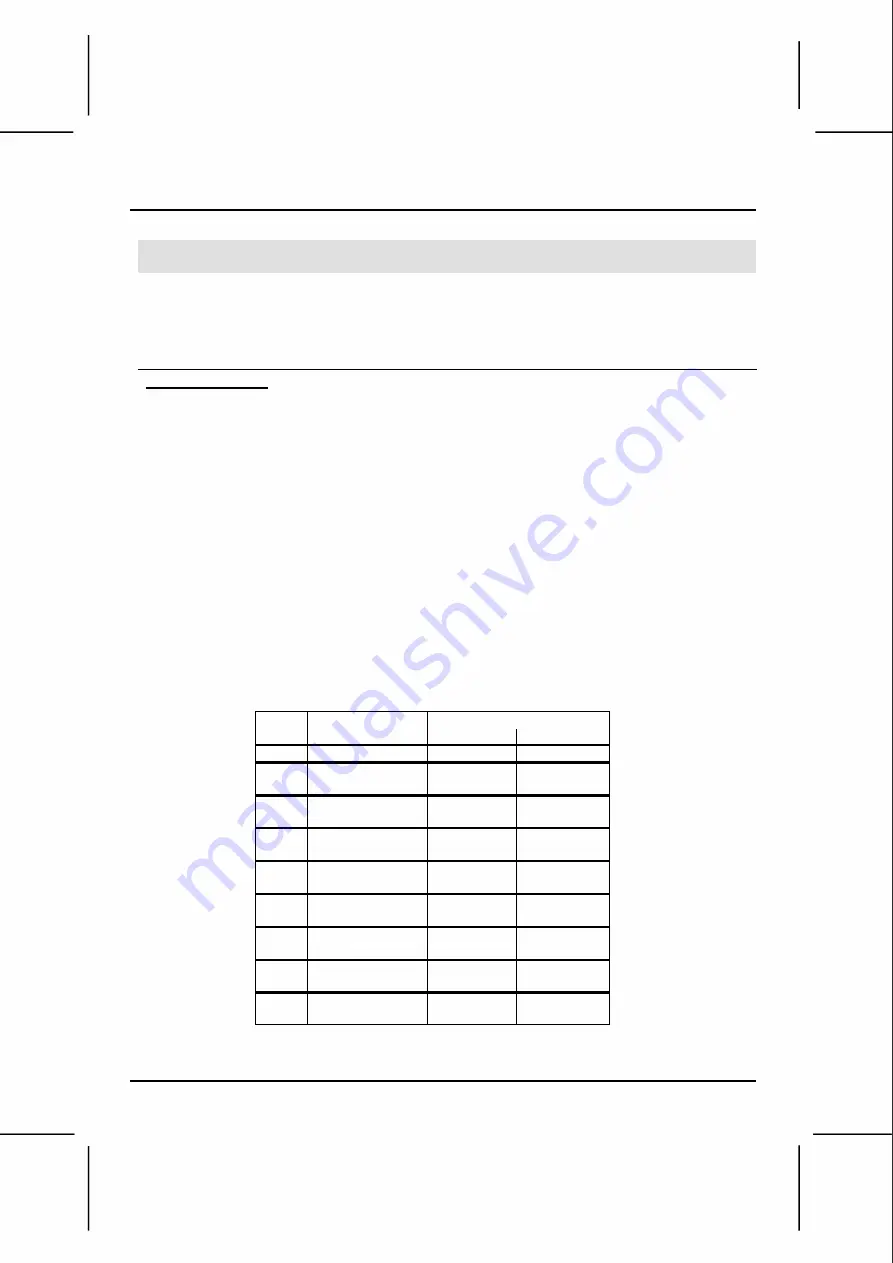
Thermocouple input ranges
Type
Temperature range
Wire color
ANSI (USA)
BS 1843 (UK)
mV
-5 to 56mV
- -
B
200 to 1820°C
+ Grey
+ None
(300 to 3276°F)
- Red
- Blue
E
-200 to 750°C
+ Violet
+ Brown
(-328 to 1382°F)
- Red
- Blue
J
-200 to 760°C
+ White
+ Yellow
(-328 to 1400°F)
- Red
- Blue
K
-200 to 1250°C
+ Yellow
+ Brown
(-328 to 2282°F)
- Red
- Blue
N
-200 to 1300°C
+ Orange
+ Orange
(-328 to 2372°F)
- Red
- Blue
R
0 to 1768°C
+ Black
+ White
(32 to 3214°F)
- Red
- Blue
S
0 to 1768°C
+ Black
+ White
(32 to 3214°F)
- Red
- Blue
T
-200 to 400°C
+ Blue
+ White
(-328 to 752°F)
- Red
- Blue
Unitronics Industrial Automation
9


