M A N U A L
Digital Battery Servo Amplifier
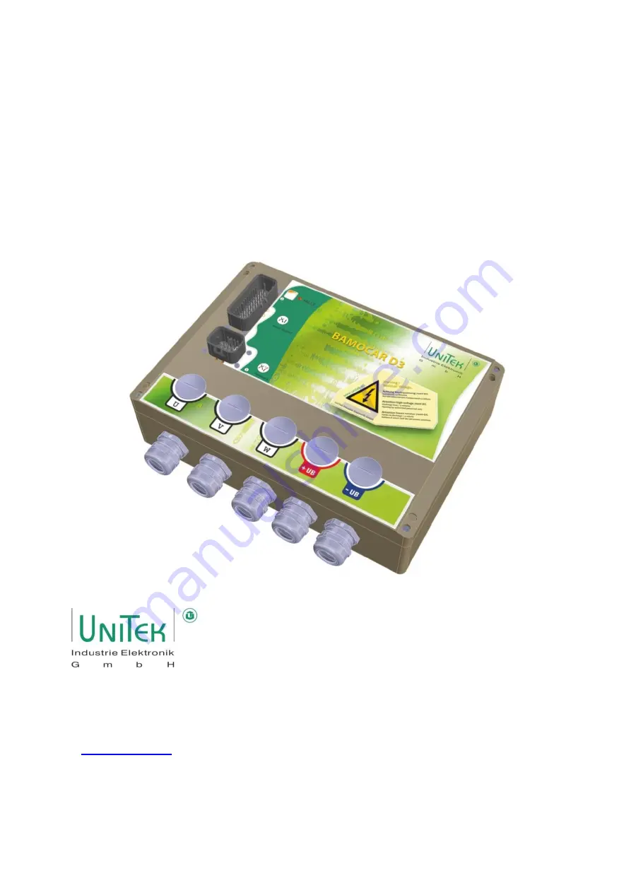
BAMOCAR-PG-D3-700-100/160
for EC servo motors
for EC asynchronous servo motors
Hans-Paul-Kaysser-Straße 1
Version
71397 Leutenbach-Nellmersbach
2021 / V1
Tel.: 07195 / 92 83 - 0
[email protected]
www.unitek.eu


