


5
INSTALLATION
A. Check that valve end joints conform to the mating pipe and verify that ends
are clean and sound. All 7700 series valves are supplied with flat face flanges
with ANSI class 125 drilling. Do not mate these valves to pipe or fittings with
raised face flanges.
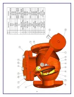
B. Remove any material used to restrain the lever or pin during shipment and
storage. Attach any outside closing mechanism in proper position manually.
C. Closing mechanism should be checked to insure freedom of motion and
proper operation. Cover bolts shall be checked for any loose joints.
D. When handling the valve, do not use the outside mechanisms for lifting.
E. It is necessary to install the valve in proper orientation with regard to flow
direction. Please note flow arrow on side of body.
F. Prepare pipe ends per pipe manufacturer’s instructions, and install valve as
per appropriate instructions for the specific joint. All piping should be properly
supported to avoid line stress on the valve. Do not use valves as a jack to force
a pipeline in position.
G. Standard wrenches and or sockets are to be used to tighten all nuts and bolts.
Fasteners are to be tightened in a crisscrossed pattern to insure balance loading
of bolts.
OPERATION
Once in the pipeline, the swing check valve will operate as flow conditions
dictate. The valve will open as the pressure on the upstream side of the disc
overcomes the downstream side. The valve will close as the situation reverses
itself or the pressure equalizes.
These valves are self contained units. Outside levers, weights, springs or hinge
pins should never be used to manually operate the valve or restrict its operation.
External shields and surrounding piping should not interfere with the free
operation of external apparatus of the valves.
MAINTENANCE
The system is designed to be trouble free with minimum care. Frequency of
inspection should be based on the operational characteristics of the system, i.e.
Summary of Contents for 7700 Series
Page 2: ...2...


