


2 /
4
P/N 1073619-EN
• REV
A
• ISS 06MAR19
Positive (+) Pin Negative (-) Pin
NS4750
-
24S
-
4T
-
4X
-
V2
Pin 1/5
Pin 2/6
Note
:
The wire gauge for the terminal block should be in the
range
from
12 to
24 AWG.
Terminal setup
To configure the system, connect a serial cable to a
COM port
on a PC or notebook computer and to
a
RJ45
type serial
port
on the
managed switch
.
Figure 3: Console connectivity
A terminal program is required to make the software connect
ed
to the managed
switch. Windows' Hyper Terminal
program
may be a good choice.
The Hyper Terminal can be accessed
from the
Start
menu.
1. Click
Start
>
Programs
>
Accessories
>
Hyper
Terminal
.
2.
When the following screen appears,
en
sure that the COM
port is
configured as
shown
below
. Click
OK
when finished
with configuration.
3. Log in to the console.
After
the terminal has
been
connected to the device, power on the
managed
switch
.
T
he terminal display
s
“running testing procedures”
.
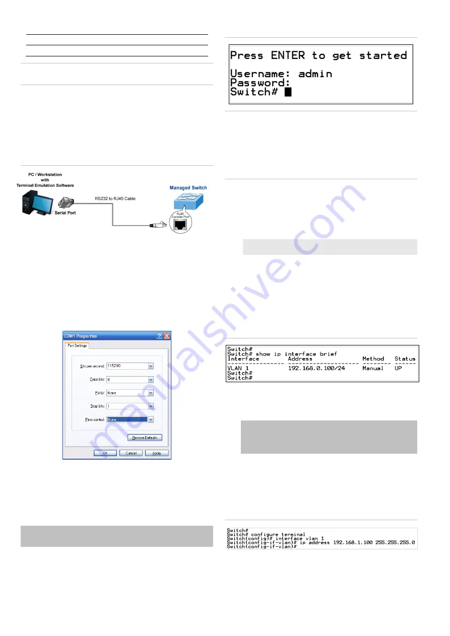
When the following dialog box in Figure
4
below
appears,
type
the
factory default user
name "
admin
" and password
“
admin
”.
User name:
admin
Password:
admin
Figure 4: Console login screen
Notes:
1.
For security purposes, change and memorize the new
password after this first setup.
Store the new password
and final configuration in a safe location for easy retrieval.
2.
Only command
s
in lowercase letter
s are accepted in the
console interface.
Configuring the IP address
The
managed switch
is shipped with
the
default
IP address
shown below:
IP
Address:
192.168.0.100
Subnet
Mask:
255.255.255.0
To check the current IP address or modify a new IP address
for the
managed
switch, use the following procedure
s:
Display of the current IP Address
1. At the “#” prompt,
type
“
show
ip interface brief
”.
2.
The screen displays the current IP address.
Figure 5: IP information screen
Configuration of the IP address
3. At the “#” prompt,
type
the following command and press
Enter
as show
n
in Figure 5
.
Switch# configure terminal
Switch(config)# interface vlan 1
Switch(config-if-vlan)# ip address 192.168.1.100
255.255.255.0
The previous command would apply the follow
ing settings
for the
managed
switch
.
IP
Address: 192.168.1.100
Subn
et M
ask: 255.255.255.0
Figure 6: Configuring the IP address screen
4
.
Repeat step 1 to check if the IP addres
s has changed.


