


43
The configurations associated with demand limiting can be
viewed at the local display at
Configuration
DMD.L
.
See
Table 48.
Demand Limit Select (
DM.L.S
) — This configuration deter-
mines the type of demand limiting.
• 0 = NONE — Demand Limiting not configured.
• 1 = 2 SWITCHES — This will enable switch input
demand limiting using the switch inputs connected to the
CEM board. Connections should be made to TB6-4, 5, 6.
• 2 = 4 to 20 mA — This will enable the use of a remote 4
to 20 mA demand limit signal. The CEM module must
be used. The 4 to 20 mA signal must come from an
externally sourced controller and should be connected to
TB6-7, 8.
• 3 = CCN LOADSHED — This will allow for loadshed
and red lining through CCN communications.
Two-Switch Demand Limiting
(
DM.L.S
= 1
) — This type of
demand limiting utilizes two discrete inputs:
Demand Limit Switch 1 Setpoint
(
D.L.S1
) — Dmd Limit
Switch Setpoint 1 (0-100% total capacity)
Demand Limit 2 Setpoint
(
D.L.S2
) — Dmd Limit Switch
Setpoint 2 (0-100% total capacity)
The state of the discrete switch inputs can be found at the
local display:
Inputs
GEN.I
DL.S1
Inputs
GEN.I
DL.S2
The following table illustrates the demand limiting (
Run
Status
COOL
DEM.L
) that will be in effect based on the
logic of the applied switches:
4-20 mA Demand Limiting
(
DM.L.S
= 2
) — If the unit has
been configured for 4 to 20 mA demand limiting, then the
Inputs
4-20
DML.M
value is used to determine the
amount of demand limiting in effect (
Run Sta-
tus
COOL
DEM.L
)
. The Demand Limit at 20 mA
(
D.L.20
) configuration must be set. This is the configured
demand limit corresponding to a 20 mA input (0 to 100%).
The value of percentage reset is determined by a linear
interpolation from 0% to
“D.L.20”
%
based on the
Inputs
4-20
DML.M
input value.
The following examples illustrate the demand limiting
(
Run Status
COOL
DEM.L
) that will be in effect based on
amount of current seen at the 4 to 20 mA input,
DML.M
.
CCN Loadshed Demand Limiting
(
DM.L.S
= 3) — If the unit
has been configured for CCN Loadshed Demand Limiting,
then the demand limiting variable (
Run Status
COOL
DEM.L
) is controlled via CCN commands.
The relevant configurations for this type of demand limiting
are:
Loadshed Group Number (
SH.NM
) — CCN Loadshed Group
number
Loadshed Demand Delta (
SH.DL
) — CCN Loadshed
Demand Delta
Maximum Loadshed Time (
SH.TM
) — CCN Maximum
Loadshed time
The Loadshed Group Number (
SH.NM
) corresponds to
the loadshed supervisory device that resides elsewhere on
the CCN network and broadcasts loadshed and redline
commands to its associated equipment parts. The
SH.NM
variable will default to zero which is an invalid group num-
ber. This allows the loadshed function to be disabled until
configured.
Upon reception of a redline command, the machine will be
prevented from starting if it is not running. If it is running,
then
DEM.L
is set equal to the current running cooling capac-
ity (
Run Status
COOL
C.CAP
).
Upon reception of a loadshed command, the
DEM.L
vari-
able is set to the current running cooling capacity (
Run Status
COOL
C.CAP
) minus the configured Loadshed Demand
Delta (
SH.DL
).
A redline command or loadshed command will stay in
effect until a Cancel redline or Cancel loadshed command is
received, or until the configurable Maximum Loadshed time
(
SH.TM
) has elapsed.
HEAD PRESSURE CONTROL — Head pressure refers to
the refrigerant pressure at the discharge side of the compressor.
Thus it is sometimes refers to as “discharge pressure.” Head
pressure control for shall be managed directly by the
Com-
fort
Link controls (no third party control).
The head pressure control stages fixed speed fans and mod-
ulating fans, if available, to maintain the head pressures of cir-
cuit A and circuit B within acceptable ranges. For controls pur-
pose, the head pressures are converted to saturated condensing
temperatures (SCTs) as the feedback information to the con-
denser fans (also referred to as “outdoor fans”).
SCT.A
is the
saturated condensing temperature for refrigeration Circuit A,
and
SCT.B
is the saturated condensing temperature for refriger-
ation Circuit B. There are a total of up to 6 condenser fans (de-
pending on unit size and installed options) for controlling the
head pressures of the 2 refrigeration circuits, of which up to 2
fans can be controlled by VFD(s) (variable frequency drive(s))
upon installation option.
The control described in this document is also referred to as
condenser fan control. Where Motormaster control is involved,
it may also referred to as low ambient control.
The low ambient control shall be directly implemented in the
Comfort
Link software. It shall not be compatible with the exist-
ing Motormaster V control as found in CESR131343-07-xx and
earlier that make use of accessory part numbers
CRLOWAMB018A00 through CRLOWAMB026A00.
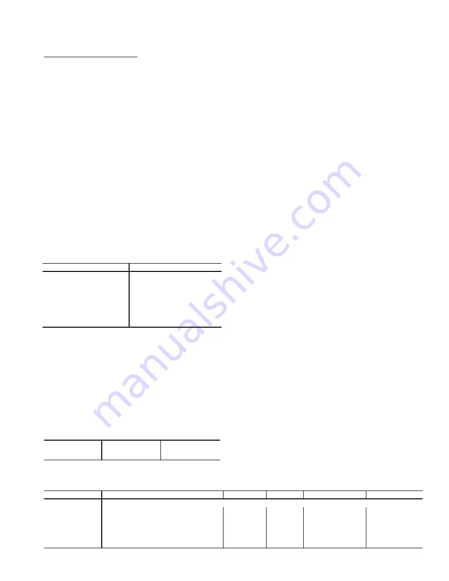
Table 48 — Demand Limit Configuration
Switch Status
Run Status
COOL
DEM.L = 1
Inputs
GEN.I
DL.S1
= OFF
Inputs
GEN.I
DL.S2
= OFF
100%
Inputs
GEN.I
DL.S1
= ON
Inputs
GEN.I
DL.S2
= OFF
Configuration
DMD.L
D.L.S1
Inputs
GEN.I
DL.S1
= ON
Inputs
GEN.I
DL.S2
= ON
Configuration
DMD.L
D.L.S2
Inputs
GEN.I
DL.S1
= OFF
Inputs
GEN.I
DL.S2
= ON
Configuration
DMD.L
D.L.S2
D.L.20
= 80%
D.L.20
= 80%
D.L.20
= 80%
DML.M
= 4mA
DML.M
= 12 mA
DML.M
= 20mA
DEM.L
= 100%
DEM.L
= 90%
DEM.L
= 80%
ITEM
EXPANSION
RANGE
UNITS
CCN POINT
DEFAULT
DMD.L
DEMAND LIMIT CONFIG.
DM.L.S
Demand Limit Select
0 - 3
DMD_CTRL
0
D.L.20
Demand Limit at 20 ma
0 - 100
%
DMT20MA
100
SH.NM
Loadshed Group Number
0 - 99
SHED_NUM
0
SH.DL
Loadshed Demand Delta
0 - 60
%
SHED_DEL
0
SH.TM
Maximum Loadshed Time
0 - 120
min
SHED_TIM
60
D.L.S1
Demand Limit Sw.1 Setpt.
0 - 100
%
DLSWSP1
80
D.L.S2
Demand Limit Sw.2 Setpt.
0 - 100
%
DLSWSP2
50
Summary of Contents for Carrier Weathermaker 48A2
Page 105: ...105 Fig 20 Typical Main Control Box Wiring Schematic 48 50A2 A3 A4 A5 Units...
Page 106: ...106 Fig 21 Typical Auxiliary Control Box Wiring Schematic...
Page 107: ...107 Fig 22 Typical 2 Stage Gas Heat Wiring Schematic Size 060 Units Shown a48 8357...
Page 108: ...108 TO NEXT PAGE Fig 23 Typical Staged Gas Heat Wiring Schematic Size 060 Units Shown A48 7296...
Page 109: ...109 Fig 23 Typical Staged Gas Heat Wiring Schematic Size 060 Units Shown cont A48 8358...
Page 110: ...110 Fig 24 Typical Electric Heat Control Schematic 50 Series Size 060 Units Shown a50 8228...
Page 111: ...111 Fig 25 Typical Power Schematic 48 50A2 A3 A4 A5 060 Unit Shown...
Page 112: ...112 Fig 26 Typical Low Ambient Controls Option Wiring...
Page 113: ...113 Fig 27 Typical Small Chassis Component Location Size 020 035 Units...
Page 114: ...114 Fig 28 Typical Large Chassis Component Locations Size 040 060 Units...
Page 118: ...118 Fig 30 Economizer Control Board ECB1 and VAV Control Board ECB2 A48 7706...
Page 142: ...142 A48 3733 Fig 56 Main Burner Removal...
Page 176: ...176 APPENDIX C VFD INFORMATION cont Fig F Internal Enclosure Fan Replacement A48 7716...


