7
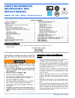
BRACKET
SHAKER GRATE HANDLE
Insert the Shaker Rod into the hole on the ash door frame as
shown. Th
en attach the Shaker Bracket to the front of the fur-
nace using two 1/4-20 x 3/4” Hex Bolts and two 1/4-20 Lock
Nuts. Next, insert the shaker Rod into the bracket and attach
to the shaker grate bar using the 1/4-20 x 1” Hex Bolt and a
1/4-20 Lock Nut. Th
e bolt and nut retaining the shaker bar and
rod should be left loose to allow free movement of the grates.
(1) Shaker Rod
(1) Shaker Bracket
(1) 1/4-20 x 1” Hex Bolt
(2) 1/4-20 x 3/4” Hex Bolt
(3) 1/4-20 Lock Nut
FRONT
SMOKE CURTAIN
SMOKE CURTAIN
CLIP
NUT
BOLT
1/4-20 NUT
SMOKE CURTAIN
CLIP
1/4-20 x 1-1/4
CARRIAGE BOLT
SMOKE CURTAIN
SMOKE CURTAIN
Using two 1/4-20 x 1-1/4” Carriage bolts, the smoke curtain
clips and two nuts, attach the smoke curtain in place above the
Fuel Feed Door as shown below. Aft er installation, the smoke
curtain should swing freely back into the furnace.
(1) Smoke Curtain
(2) Smoke Curtain Clips
(2) 1/4-20 x 1-1/4 Carriage Bolt
(2) 1/4-20 Kep Nut
SPRING HANDLES
Attach the four(4) spring handles to the Feed/Ash Doors, Baffl
e
Rod, and Shaker Rod by twisting the springs counter-clockwise
while applying pressure until you have screwed them approxi-
mately 3/4”-1” onto the rods.
(4) Spring Handles
DISTRIBUTION BLOWER & ACC.
1. Remove all contents and insure that all components are
present for assembly. See the part list below
2. Begin by attaching the blowers to the unit. Insert a clip into
each mounting hole in the furnace’s cabinet back. Be sure
to install the gasket between the blower and cabinet back.
Insert the eight bolts provided and tighten.
3. Mount the Honeywell limit control to the cabinet back.
Th
e conduit assembly should already be attached to the
limit control, otherwise, do so then make the correct wir-
ing connections to the limit control. See wiring diagram.
4. Next, mount the junction box and insulation using two of
the #10 x 1/2 screws provided. Make a small slice in the
5 x 5 insulation to allow the wires from the draft blower
to protrude, then Install it between the cabinet back and
junction box, with the foil side to the cabinet back. Attach
the conduit assembly from the limit control to the junction
box as shown.
5. If not already installed, snap the rocker switch into the top
of the junction box. Provide a 110 volt power supply and
connect to the junction box with the cable clamp to the
right side.
6. Attach the two longer conduit assemblies to the junction
box and to each blower.
7. Before mounting the Fan Center, make all the wire con-
nections per the wiring diagram, then attach the fan center
to the junction box. All electrical connections should be
done by a qualifi ed electrician.