


IMP120-17
www.ueonline.com
Option M210 Indicator for Differential Pressure Controls,
Span Adjustment
(See Figure 6). To adjust indication for maximum accuracy at any
desired set point, follow steps 1 thru 3 listed below:
1. Remove front window and gasket (four screws) to gain access
to span adjustment.
2. Connect device to calibrated gauge and set required differential
pressure.
3. Using a screwdriver, slowly turn the span adjustment to obtain
required indication. Remount the front gasket and window.
NOTE:
Spanning adjustment will not affect the mid-range indication.
The adjustment is factory calibrated and sealed to indicate tampering.
DO NOT FORCE SPAN ADJUSTMENT, SINCE PERMANENT
DEFORMATION OF THE LINKAGE MECHANISM MAY RESULT.
RE-GAPPING PROCEDURE
Tools Needed
5/8” Open End Wrench
3/16” Open End Wrench (2)
GAPPING IS FACTORY-SET AND CRITICAL TO THE FUNCTION
OF THE SWITCH. THIS PROCEDURE SHOULD ONLY BE
PERFORMED IF THE PLUNGER HAS ACCIDENTALLY BEEN
ADJUSTED.
1. Loosen adjustment lock.
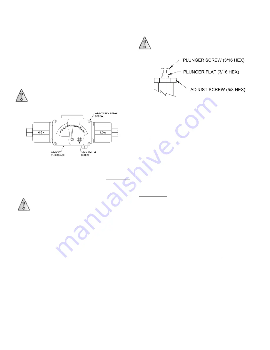
2. Turn 5/8” hex adjustment screw clockwise to approximately
midrange. This puts a load on the sensor and exposes the
plunger flats. (See Figure 7).
3. Using a 3/16” wrench on the plunger flats and a 3/16” wrench on
the plunger hex screw, turn hex counter-clockwise from plunger
until micro-switch actuates. If microswitch has already actuated,
turn plunger hex screw clockwise until microswitch deactuates.
4. Continue per following instructions, depending on model.
Models 171-174, 521-525, 531-535, and 540-548
Turn hex clockwise an additional 1-1/2 flats from this point. This will
provide a 5-9 mil gap.
Models 680, 701-705, 356-376, 612, 616, 270, 274
Turn hex clockwise 3 flats from this point (approximately 1/2 turn).
This will provide a 14-16 mil gap.
Re-Gapping Procedure for J120/J120K
Figure 7
Models 183-189, 190-194, 483-489, 490-494,565-567
Turn hex clockwise 1 flat from this point. This will provide a 4-7 mil
gap.
CONTACT FACTORY FOR ASSISTANCE WITH MODELS
NOT SHOWN ABOVE.
ZONE HAZARDOUS LOCATIONS FLAMEPROOF GAP AND JOINT
DETAILS
120’S
Activation Plunger to adjustment screw hole gap joints: 1.140in/28.96mm
min length by 0.0039in/0.099mm max annular gap
Plunger Guide to enclosure through threaded joints: minimum 8 ½ fully
engaged threads
Cover to enclosure through threaded joints: minimum 7 ½ fully engaged
threads
121’S & 122’S
Activation Plunger to enclosure through hole gap joints: 1.000in/25.40mm
min length by 0.0030in/0.076mm max annular gap
Adjustment shaft to shaft through hole gap joints: 1.050in/26.67mm min.
length by 0.0035in/0.089mm max. annular gap
Cover to enclosure through threaded joints: minimum 7 ½ fully engaged
threads
MANUAL RESET OPTION 1530 (120’S,121’S)
Reset pivot to pivot guide through hole gap joints: 1.118in/28.40mm min.
length by 0.0036in/0.091mm max annular gap
Reset guide to enclosure through threaded joints: 8 fully engaged threads
Figure 6
Option M210


