MAINTENANCE
Pointed tip needles
Sharpened to a nail point, these are most
effective in breaking through very hard scale
on surfaces where some surface indentation
is permissible - or where keying (i.e. profile) of
the surface is desirable.
Pointed tip needles are available in 3mm and
4mm only.
Chisel tip needles
These are general purpose needles, flattened
to a chisel like blade and are most effective in
the removal of thicker material, while leaving a
less pitted surface than the Pointed tip
needles but still giving some surface
indentation (i.e. profile).
Chisel tip needles are available in 3mm only.
Flat tip needles
Machined to a flat tip, these needles will leave
slight marking (i.e. profile) on the surface; the
2mm needles can have a burnishing effect.
2mm Needles are recommended for use on
thin gauge metals and any surface where light
treatment is desired.
Flat tip needles are available in three sizes -
2mm, 3mm and 4mm.
SEE SPECIFICATION SECTION FOR
QUANTITIES.
Fitting the
Chisel Holder
(Non TVS)
Before fitting the Chisel Holder (31),
disconnect the tool from the air supply,
slacken the pinch bolt on the Needle Holder
Assembly and remove the assembly, taking
care not to allow the internal components to
fall out.
To fit the Chisel Holder (31) ensure that the
pinch bolt (30) on the Chisel Holder (31) is
loose, screw the Chisel Holder (31) fully on to
the Cylinder (10) or Body (13).
Then unscrew to position the boss
underneath.
Turn the knurled collar on the Chisel Holder
(31) until the retaining ball is fully visible;
insert the Chisel (32) aligning the rebate with
the ball.
Position the midpoint of the rebate on the
shank of the Chisel (32) with the retaining ball
and turn the collar half a turn to lock the
Chisel (32) in place.
Tighten the pinch bolt (30) using a 6mm AF
Allen key. To release the Chisel (32), rotate
the knurled collar until the retaining ball is fully
visible and remove the Chisel (32).
Fitting of the Needle Scaler Attachment
Before fitting the Needle Scaler Attachment,
disconnect the air supply from the tool,
slacken the pinch bolt on the Chisel Holder
and remove Chisel Holder.
Assemble the component parts of the Needle
Scaler attachment in the following order;
insert the Needles (26) into the Needle Holder
(25),
place the Spring (27) over the Needles, insert
the Anvil (24), small diameter first, into the
Needle Holder (25), then place the assembly
into the Intermediate Tube (28).
Check the service layout for clarification.
Screw the assembly fully onto the Cylinder
(10) or Body (13) and tighten the pinch bolt
(30) using a 6mm AF Allen key.
Slide the Front Tube (29) on to the
Intermediate Tube (28) until approximately
25mm (1”) of Needle protrudes from the Front
Tube (29). Tighten the pinch bolt (30) using a
6mm AF Allen key.
Dismantling
Remove all deposits from outside of the
Needle/Chisel Scaler and disconnect the tool
from the air hose.
Slacken the pinch bolt on the Needle Holder
Assembly or Chisel Holder and carefully
unscrew from the Body/Cylinder.
Take care not to allow the internal
components to fall out of the Needle Holder
Assembly.
All Valve Body Servicing
Clamp the Valve Body (6) firmly in a vice,
using the flats provided, and with the Throttle
Lever (7) upper most.
Using a 3mm diameter pin or punch and small
hammer, remove the Throttle Lever Roll Pin
(8), and remove the Throttle Lever (7).
Rotate the Valve Body (6) 180 degrees in the
vice to gain access the Valve Cap (1).
Unscrew the Valve Cap (1) using a
screwdriver, check the Valve Cap O’ Ring (2)
for signs of deterioration, remove the Spring
(3), push out the Valve Stem (4) and remove
the valve seat O’ Ring (5).
Check the Valve Stem (4) and O’ Ring (5) for
wear.
Piston and Cylinder removal
To remove the Piston (9) or Cylinder from
each of the three styles of Needle/Chisel
Scaler, refer to the specific instructions below.
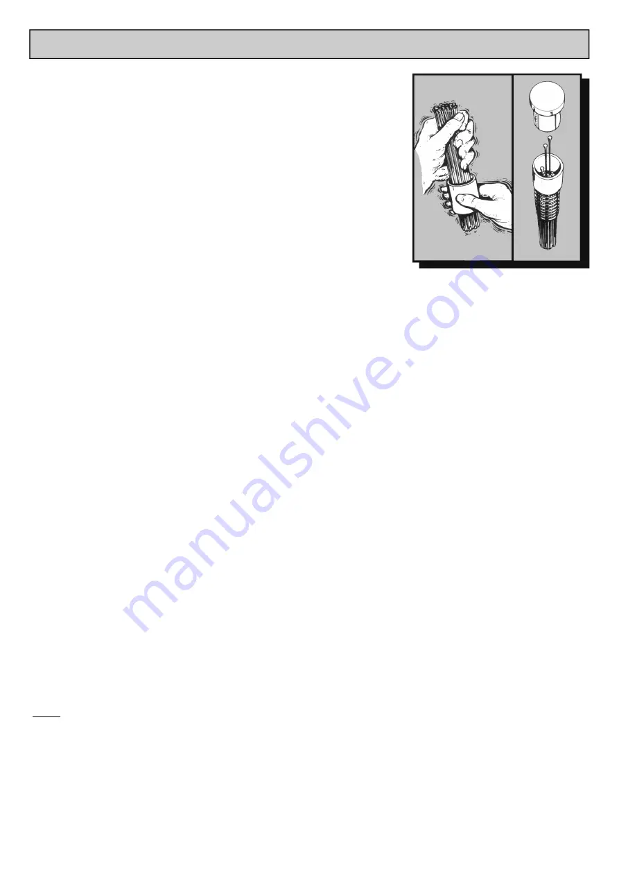
Hold the needles loosely
and shake the holder,
needles will fall into location
holes
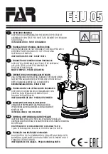
The correct
position of parts
when changing
needles
Never allow the tool to run continuously
whilst not in contact with the surface being
prepared.
Maintenance
Only a competent person, in a suitably
equipped workshop, must carry out
maintenance.
Disconnect the tool from the air supply
before carrying out any maintenance or
any of the operations in the next sections
.
Clean all debris from the exterior of the tool.
For safe efficient running and at intervals of
no more that 100hrs or if operation becomes
sluggish, dismantle and clean with highly
refined paraffin. Immediately after cleaning,
thoroughly oil the tool with one of the
recommended lubricants.
Changing
Needles
Before changing or replacing needles,
disconnect the air supply to the tool.
Loosen the Cap Head Screw (30) on the
Intermediate Tube (28) and remove the Tube
Assembly, taking care not to allow the internal
components to fall out.
Please note:
Take note when disassembling how all the
parts inside the Intermediate Tube (28) fit
together as wrong assembly will result in
damage to the tool.
Remove the Needle Holder (25) and Anvil
(24) as an assembly
from the Intermediate
Tube, check that the Return Spring (27) fitted
inside the Intermediate Tube is in good
condition.
Remove the Needles from the Needle Holder
and replace with new Needles as per the
illustration.
On assembly ensure that the small diameter
of the Anvil (24) fits inside the Needle Holder
(25).
Place the Return Spring over the Needles and
fit the assembly into the Intermediate Tube.
Fully screw/push the Tube Assembly onto the
Body/Cover.
Note:
The 2BPG has a grip thread.
Position the boss underneath and tighten the
Allen Screw (30).
As the Needles wear, adjust the Vacuum
Tube by loosening the Allen Screw and
adjusting the Tube so that when the tool is
running approximately 10 - 20mm of Needle
protrudes from the Front Vacuum Cuff and
then retighten the Allen Screw.
1-800-700-5919 (US/CA)
WWW.CSUNITEC.COM
+1-203-853-9522 (Intl.)


