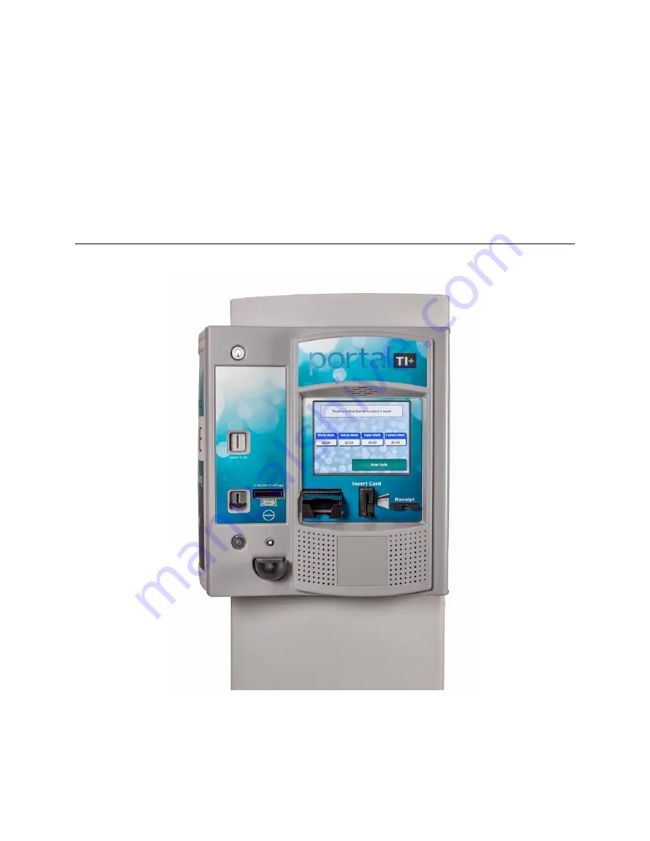
Portal
®
TI+
Installation Manual
Unitec
443-561-
1200 • www.StartwithUnitec.com
Page 1: ...Portal TI Installation Manual Unitec 443 561 1200 www StartwithUnitec com ...
Page 2: ... 15 of the FCC Rules These limits are designed to provide reasonable protection against harmful interference when the equipment is operated in a commercial environment This equipment generates uses and can radiate radio frequency energy and if not installed and used in accordance with the instruction manual may cause harmful interference to radio communications Operation of this equipment in a res...
Page 3: ...ended Tools 7 2 2 1 Mechanical Installation Tools 7 2 3 Base Installation 8 2 4 Brick In Installation 9 2 4 1 Brick in Mounting Options 9 2 4 2 Positioning the Portal 10 2 4 3 Brick in Guidelines 13 3 Electrical Installation 17 3 1 Hardware Required 17 3 2 Recommended Tools 17 3 3 General 17 3 4 Connecting Power 18 3 5 Network Connection 20 3 6 Telephone Cable 21 3 7 Wash Control Wiring 22 3 7 1 O...
Page 4: ...10 Figure 8 Positioning the Adaptor Plate 11 Figure 9 Door Positioning Options 12 Figure 10 Portal Mounting for Bricked In Installation 13 Figure 11 Portal Brick In with Adaptor Plate 14 Figure 12 Portal Brick In with Adaptor Plate on Base Frame 15 Figure 13 Portal Interior 18 Figure 14 Inside the AC Connector 19 Figure 15 Line Neutral Ground Connections 19 Figure 16 Network Port Location 20 Figur...
Page 5: ...ned to be embedded in a concrete pad and as such should be installed when concrete is poured at the site In cases where the concrete is already in place it s recommended that holes be drilled into the concrete to secure the legs of the base frame Refer to section 2 3 for base installation instructions The brick in option includes an adaptor plate that s designed to provide the proper air circulati...
Page 6: ... the curb To achieve this dimension the base frame should be installed so its leading edge is 8 in from the edge of the curb as shown in Figure 2 Figure 2 Frame Location for Curb Mount 1 3 2 Express Wash Applications Express Exterior sites should be designed to provide 9 ft wide traffic lanes at the Portals The traffic control or barrier gate should be located approximately 10 ft from the center o...
Page 7: ...e referred to as the merge loop to properly manage the vehicle queue If the Unitec ReachFree ID RFID option is included the RF Antenna should be located adjacent to the Portal Figure 3 provides guidelines for the design of an Express lane with the Portal gate and RFID antenna option Refer to the installation instructions provided with the gate and RFID option for guidance in installing these devic...
Page 8: ...al RFID option are to be used Conduit size should be at least in a larger conduit may be required depending on the quantity and gauge of wires to be installed Refer to local and national electrical codes to select the proper conduit type and size Figure 4 provides guidelines for conduit planning Figure 4 Conduit Runs To ensure the conduit sections will be located within the Portal base and not int...
Page 9: ... Its designed so that wires and or conduit can be routed into the Portal through the round conduit holes on the top However it will be far easier to bring the conduit stubs into the frame through the large rectangular cut outs on the bottom plate You can then attach flex conduit between the stubs and conduit holes on the top panel or just run the wires from the stubs up through these holes ...
Page 10: ...stub Circuit Description Wire Qty Wire Requirements Portal Power 115 120 VAC 8 Amps 3 16 AWG minimum black white green Gate Power 115 120 VAC 5 Amps 3 16 AWG minimum black white green Network connection to router 1 Cat 5 communications cable 295 ft max length Wash Signaling required if the Portal will be connected to the wash controller Varies Refer to wash equipment manufacturer s instructions Ph...
Page 11: ...ale AC Power Connector Items supplied with the Base 3 Hex Nuts 3 Flat Washers 3 Lock Washers Items supplied with the Brick in Option Adapter Plate 4 J Bolts and nuts for securing the adapter plate 3 x 1 Hex Bolts 3 Flat Washers 3 Lock Washers 2 2 Recommended Tools 2 2 1 Mechanical Installation Tools The following tools are recommended for the typical mechanical installation of this Portal TI unit ...
Page 12: ...d that the concrete pad be undercut as illustrated in the figure below This type of installation provides greater security The undercut pad size should have the following dimensions Pad Dimension Requirements Minimum Recommended Surface Width 18 48 Undercut Depth 8 24 Figure 6 Base Installed in Concrete Pad To ensure the base is installed at the proper height the lower cross braces should be flush...
Page 13: ...ed wires are routed to a point where they can be accessed and pulled through the wiring holes on the bottom of the Portal Carefully set the Portal on top of the base so the 3 studs of the base pass through the mounting holes on the bottom of the Portal Secure the Portal to the studs with the flat washer lock washer and hex nut in that order supplied with the base Pull the wires up through the cabl...
Page 14: ...re as shown in Figure 8 The adapter plate has 2 sets of mounting holes One set is used to install the Portal so its front door will be flush with the brick The other set is used to recess the door within the brick These 2 mounting options and hole patterns are illustrated in Figure 9 and Figure 10 Electrical conduits should be extended to the adapter plate and positioned so wiring can be routed th...
Page 15: ...P O R T A L T I Portal Installation Manual 11 Document PTL1001 Figure 8 Positioning the Adaptor Plate ...
Page 16: ...P O R T A L T I Portal Installation Manual 12 Document PTL1001 Figure 9 Door Positioning Options ...
Page 17: ...high 8 rows of bricks from the pavement 2 Fill the enclosure with concrete 3 Sink the Adaptor Plate with Mounting Bolts into the wet concrete Position the Adaptor Plate 4 back from the front edge of the brick Level the Adaptor Plate while the concrete is still wet 4 After the concrete has cured secure the Portal TI to the Adaptor Plate with the 3 flat washers lock washers and bolts supplied with t...
Page 18: ... u r b He i g h t F r a m e Follow the base installation instructions in section 2 3 to set the base frame in the concrete The adapter plate attaches to the 3 studs on top of the frame with nuts and washers Position the frame so the front of the adapter plate will be recessed 4 5 from the front face of the brick as shown in Figure 12 ...
Page 19: ...P O R T A L T I Portal Installation Manual 15 Document PTL1001 Figure 12 Portal Brick In with Adaptor Plate on Base Frame ...
Page 20: ...P O R T A L T I Portal Installation Manual 16 Document PTL1001 T H I S P A G E I N T E N T I O N A L L Y L E F T B L A N K ...
Page 21: ...ll be a number of electrical connections that must be made These connections will require the use of the following common electrical tools Small thin tipped straight screwdriver 1 8 tip for green Phoenix connectors Wire strippers capable of handling 10 23 AWG wire Diagonal cutters Needle nose pliers Modular plug crimp tool if CAT 5 or phone lines need to be terminated Note When performing the inst...
Page 22: ...on the right hand side of the Portal TI case 1 Locate main power wires There will be three 16 AWG or greater environmentally rated black white and green colored wires 2 Route the main power wires to the Portal s input power connector and remove excess wire length leaving sufficient length to reach the AC power inlet 3 Remove the 3 pronged AC connector from the AC power inlet supplied with the Port...
Page 23: ...the wires 6 Thread the power wires through the strain relief 7 Remove the white stabilizer plate 8 Secure the Line Black Neutral White and Ground Green wires to the appropriate terminal screws See Figure 23 Re tighten the screws to hold the wires in place Figure 15 Line Neutral Ground Connections 9 Re assemble the AC connector and insert it into the power inlet Use wire ties to route and secure th...
Page 24: ...e with a modular RJ 45 plug The Network Ethernet port is located at the bottom edge of the carrier board as shown in Figure 16 There should be a surge suppressor installed in the Ethernet port Insert the terminated CAT 5 cable into the other end of the surge protector The facility end of the Cat 5 cable connects to one of the LAN ports on the Unitec router The router s WAN port should be connected...
Page 25: ... crimping tool proceed to make a solid connection between the RJ 11 connector not included and the conductors of the phone cable Any unused conductors should be trimmed back with a pair of diagonal cutters so that they are even with the outer insulation 4 Terminate the other end of the cable in the same manner Note that the wires must be installed into each connector in the same order The telephon...
Page 26: ... to provide the arming signals for the selected wash packages One common line and four arming input wires are fed from the wash s PLC to the Wash I O board Each of the four arming input wires signal the equipment to give only the designated wash options When a customer purchases a wash package the Portal TI sends a signal down the appropriate arming input wire through the Wash I O board In additio...
Page 27: ...or the Wash Select II wash interface 3 7 2 1 P r e p a r a ti o n You will need a thin tipped flat head screwdriver to open and tighten the relay connections of the Phoenix connector Review the wash manufacturer s documentation to determine the color codes for the wiring of the wash pin outs for your wash equipment before beginning this installation Phoenix connectors are shipped already inserted ...
Page 28: ...ors 4 Remove the Phoenix connector from the socket 5 Turn the connector so that the wire inputs are facing up as shown below Figure 20 10 Pin Phoenix Connector Note Wash Output refers to the number associated with the arming wires Refer to the wash manufacturer documentation for more information ...
Page 29: ...ector into the Wash I O board socket J17 8 Continue to Wash In Use wiring procedures 3 7 3 Wiring the Wash In Use Interface Note Follow local electrical code when wiring the Portal TI Wash equipment requires a reset circuit This circuit is generally identified as the Wash In Use WIU signal It is not uncommon for values of this voltage to be as much as 115 120 VAC so it is extremely important to ve...
Page 30: ...rner of the Wash I O board 2 Remove the Phoenix connector from the socket 3 Turn the connector so that the wire inputs are facing up as shown below Figure 21 6 Pin Phoenix Connector 4 Referring to the figure above connect the following wires to the appropriate pins as indicated in the following table Use the screwdriver to open and or secure the manufacturer wash wires to each of the Unitec relay ...
Page 31: ...d the mode of operation J34 is the interface and connects to the customer s intercom unit J35 is used to select mode of operation two three or four wire intercom systems Twisted pair fully shielded cable is recommended for optimum performance 3 8 3 Intercom Adjustments The Intercom system has the ability to sense when voice band audio signals are present This allows the speakers in the unit to rev...
Page 32: ...t closure of RL5 This is the default for the four wire mode when both the call function and audio are completely separated More detailed instructions on this follow Audio When the Portal intercom mode is active the audio section is floating and is not relative to ground By default J34 Pin 3 SP and J34 Pin 4 SP will always be connected to the audio section Four Wire Intercom Configuration Two separ...
Page 33: ...n This mode uses a common ground for both audio and the call function SP Jumper pins 3 4 of J35 and connect H1 SP and SP as shown below Figure 24 Three Wire Intercom Configuration 2 Wire Intercom Configuration This type of intercom system has both the Call Function and audio sharing the two conductors Jumper pins 3 4 and 1 2 of J35 and connect the two conductors to SP SP as shown below Figure 25 T...
Page 34: ...connector similar to the one shown in Figure 26 Figure 26 BNC Male Plug for Camera Connection 3 10 Gate Wiring In multi lane applications a Unitec or 3rd party gate controller is required Refer to the instructions provided with the gate controller for connecting wires between it and the Portal If needed a gate can be used with a single Portal and no gate controller Refer to the Portal TI CAME Sing...
Page 35: ... tests in maintenance mode Washes and added services are properly configured and wash outputs are properly wired The wash fault out of service signal places the Portal out of service Portal Ethernet communications through the Cat 5 cable Credit card processing Note The merchant should confirm credit card revenues are being properly deposited to their account Functionality of peripherals POS interf...
Page 36: ...P O R T A L T I Portal Installation Manual 32 Document PTL1001 T H I S P A G E I N T E N T I O N A L L Y L E F T B L A N K ...
Page 37: ...Portal Installation Manual 33 Document PTL1001 Appendix A Dimensional Schematic of the Portal TI Figure 25 Bottom View of the Portal TI ...
Page 38: ...P O R T A L T I Portal Installation Manual 34 Document PTL1001 ...
Page 39: ...nfigured at Unitec with the merchant account and processor information To install the IPTran you will first mount it to the hopper cage and then connect the power and communications cables M o u n t t h e D a t a Tra n 1 Mount the modem bracket to the screws located on the side of the hopper cage Location of IPTran Modem 2 Slide the DataTran into the mounting bracket with the cable ports facing fo...
Page 40: ...IPTran Wiring 1 Connect the CAT5 line to the Datatran 2 Connect the modem communication cable to the communications port on the DataTran 3 Plug the other end of the communications cable with the DB9 connetor into Com 3 Port A of the Carrier Board This is the top DB9 input labeled CN11 Channel A ...
Page 41: ...e power supply cord into the power inlet on the modem 5 Plug the power supply cord into the power outlet in the power supply located on the back of the Portal case 6 Refer to Credit Netwrok setup in the Sierra Management Application Programming Manual to configure the server to recognize the IPTran modem ...
Page 42: ...d to be added The WAN port of the switch connects to one of the LAN ports of the Unitec router The additional devices can then be connected to the LAN ports of the switch The illustration below provides a sample network diagram Example of Networked Unitec Devices Third party devices should not be connected directly to the Unitec router The broadband device supplied for internet Service e g DSL or ...
Page 43: ...w external connections to and from the Portal The router should be configured to Forward the ports assigned to the Portal s to the Unitec router For a single unit installation the port is 9810 In multi unit sites the ports would increment for each Portal i e 9811 9812 etc Provide a static reserved IP address to the Unitec router reserved so that the forwarded ports will always be directed to it ...
Page 44: ... cable by holding the sheath in one hand and pulling sideways with the string or wire Cut away the unzipped sheath and cut the twisted pairs about 1 1 4 30 mm You will notice 8 wires twisted in 4 pairs Each pair will have one wire of a certain color and another wire that is white with a colored stripe matching its partner this wire is called a tracer 2 Inspect the newly revealed wires for any cuts...
Page 45: ...reen white brown brown 5 Press all the wires flat and parallel between your thumb and forefinger Verify the colors have remained in the correct order Cut the top of the wires even with one another so that they are 1 2 12 5 mm long from the base of the jacket as the jacket needs to go into the 8P8C connector by about 1 8 meaning that you only have a 1 2 of room for the individual cables Leaving mor...
Page 46: ...also enter the rear of the jack about 1 4 6 mm to help secure the cable once the plug is crimped You may need to stretch the sleeve to the proper length Verify that the sequence is still correct before crimping 7 Place the wired plug into the crimping tool Give the handle a firm squeeze You should hear a ratcheting noise as you continue Once you have completed the crimp the handle will reset to th...
Page 47: ...001 computers or phone system equipment making it even more crucial that the pairs are in the correct order A simple cable tester can quickly verify that information for you Should you not have a network cable tester on hand simply test connectivity pin to pin ...
Page 48: ... HP LaserJet 3300 HP LaserJet 4000 series HP LaserJet 4100 series HP LaserJet 4200 series HP LaserJet 4300 series HP LaserJet 5000 series HP LaserJet 5100 series HP LaserJet 8000 series HP LaserJet 9000 Brother HL5200 Series Note If you wish to use a different printer make sure that it is compatible with the printer driver HP PCL5 or greater I n s t al l ati o n Pr o ce d u r e s 1 Connect the USB...
Page 49: ...P O R T A L T I Portal Installation Manual 45 Document PTL1001 ...
Page 50: ...connects to the C store POS System A standard 9 pin serial cable is included with the POS device but some systems may require an alternate cable or adapter Contact the POS manufacturer for their cabling requirements Refer to Appendix C for guidance in connecting the External POS device to the Unitec router Refer to the Sierra Management Application Programming Manual for for instructions on config...