Unisource PS-2303 Operation Manual Download Page 12


- 10  -

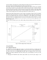
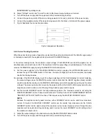
to the load change. The intersection of constant voltage and constant current modes is called the crossover 
point. Fig.5-1 shows the relationship between this crossover point and the load. 
For example, if the load is such that the power supply is operating in the constant voltage mode, a regulated 
output voltage is provided. The output voltage remains constant as the load increases up until the point where 
the preset current limit is reached. At that point, the output current becomes constant and the output voltage 
drops in proportion to further increases in load. The point is indicated by the front panel LED indicators. The 
crossover point is reached when the CV indicator goes off and the CC indicator comes on. 
 
Similarly, good example of this would be seen when charging a 12-volt battery. Initially, the open circuit voltage 
of the power supply may be preset for 13.8 volts. A low battery will place a heavy load on the supply and it will 
operate in the constant current mode, which may be adjusted for a 1 amp charging rate. As the battery 
becomes charged, and its voltage approaches 13.8 volts, its load decreases to the point where it no longer 
demands the full 1 amp charging rate. This is the crossover point where the power supply goes into the 
constant voltage mode. 
Crossover from the constant current to the constant voltage mode automatically occurs from a decrease in 
load.  


Fig.5-1 Constant Voltage/Constant Characteristic 


5-4. Operation Mode


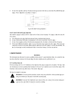
5-4-1. Independent Operation 

The "MASTER" and "SLAVE" supplies each provide a 0 to rating volts output at up to rating amps. This 
procedure covers the use of the MASTER and SLAVE supplies only when they are used independently from 
one another. When used in the INDEPENDENT operating mode, the operating controls of the two power 
supplies are completely independent and either supply can be used individually or both can be used 
simultaneously. 
A.  Disengage both TRACKING mode switches (both switches out) so that the power supply is in the 

Summary of Contents for PS-2303

Page 1: ...Multi channel DC Power Supply PS 303DU 305DU 3010DU 6005DU PS 2303 2305 Operation Manual V1 0 BENCHTOP INSTRUMENT...

Page 2: ...ear Panel Control 8 5 OPERATION INSTRUCTIONS 9 5 1 Precaution 9 5 2 Setting Current Limit 9 5 3 Constant Voltage Constant Current Characteristic 9 5 4 Operation Mode 10 5 4 1 Independent Operation 10...

Page 3: ...at the maximum output current or can be continuously adjusted throughout the output range The front panel current controls can be used to establish the output current limit overload or shout circuit...

Page 4: ...05DU 0 60V x2 0 5A x2 Built in 16 Dimensions PS 3010DU 6005DU 255Wx155Hx460D mm PS 303DU 305DU 2303 2305 255Wx155Hx330D mm 3 SPECIFICATIONS 3 1 Operation Mode 1 Independent Two independent outputs and...

Page 5: ...0mV Fixed output Output voltage 5V 0 25V Output current 3A Load regulation 25mV 110 220VAC rated input Ripple noise 2mVrms 5Hz 1MHz Display Voltmeter 3 digits 0 4 LED display Ammeter 3 digits 0 4 LED...

Page 6: ...4 Fig 4 2 b PS 2303 2305 Front panel Fig 4 2 c PS 3010DU 6005DU Front panel...

Page 7: ...5 Fig 4 3 d PS 303DU 305DU Rear panel Fig 4 4 e PS 2303 2305 Rear panel...

Page 8: ...6 Fig 4 5 f PS 3010DU 6005DU Rear panel Fig 4 6...

Page 9: ...when the MASTER supply is in the constant current operation 13 C C indicator Lights when the SLAVE supply is in the constant current operation Also lights when the TRACKING PARALLEL mode is selected 1...

Page 10: ...tput terminal for 5V supply 24 Output terminal Negative polarity output terminal for 5V supply 29 Output indicator Lights when switch is engaged in 30 Output ON OFF switch DC power supply output when...

Page 11: ...efore adding load adjust the voltage knob to the minimum value then turn on the instrument Next turn the voltage current adjustment knob to set targeted values 3 Output voltage overshoot Voltage betwe...

Page 12: ...ry will place a heavy load on the supply and it will operate in the constant current mode which may be adjusted for a 1 amp charging rate As the battery becomes charged and its voltage approaches 13 8...

Page 13: ...double the displayed value For example if the MASTER display is set for voltage metering and the SLAVE display for current metering the output voltage across the MASTER positive red terminal and the S...

Page 14: ...nly the MASTER output terminals are used for parallel tracking operation In the parallel tracking mode the SLAVE supply output voltage and current are tracking the MASTER supply output voltage and cur...

Page 15: ...correct this situation the load on the supply must be decreased so that no more than 3 amps of current are sucked 6 MAINTENANCE WARNING The following instructions are for use by qualified personnel on...

Page 16: ...Make sure the power cord is unplugged 2 Change the AC select switch to the desired line voltage position 3 A change in line voltage may also require a corresponding change of fuse value Install the c...

Reviews: