151
Note
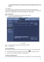
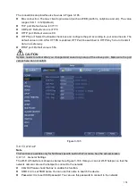
Destination IP and port refers to NVR IP address and port. System can auto get and display.
Step 3 Click OK to complete setup.
⚫
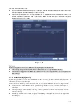
Connection mode is RS232 or RS485.
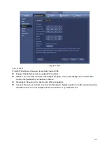
Step 1 Click Setup.
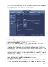
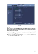
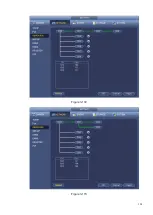
Enter Setup interface. See Figure 3-162.
Figure 3-162
Step 2 Set address, baud rate, data bit, stop bit and parity.
Note
Make sure the parameters here are the same with the POS setup.
Step 3 Click OK to complete setup.
3.8 Network
3.8.1 Network Settings
3.8.1.1 TCP/IP
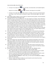
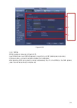
The single network adapter interface is shown as in Figure 3-163 and the dual network adapters interface
is shown as in Figure 3-164.
⚫
Network Mode : Includes multiple access, fault tolerance, and load balancing
Multiple-address mode: eth0 and eth1 operate separately. You can use the services such as
HTTP, RTP service via etho0 or the eth1. Usually you need to set one default card (default setup
is etho) to request the auto network service form the device-end such as DHCP, email, FTP and
etc. In multiple-address mode, system network status is shown as offline once one card is
offline.
Summary of Contents for EmPower NVR
Page 1: ...EmPower NVR User s Manual V4 4 3...
Page 36: ...23 Figure 3 16 Step 2 Click device display edit interface See Figure 3 17...
Page 97: ...84 Figure 3 91 Figure 3 92...
Page 120: ...107 Figure 3 110 Figure 3 111 Figure 3 112...
Page 131: ...118 Figure 3 123 Figure 3 124...
Page 133: ...120 Figure 3 126 Click draw button to draw the zone See Figure 3 127...
Page 137: ...124 Figure 3 130 Click Draw button to draw a zone See Figure 3 131 Figure 3 131...
Page 142: ...129 Figure 3 136 Click draw button to draw the zone See Figure 3 137...
Page 155: ...142 Figure 3 149 Figure 3 150...
Page 156: ...143 Figure 3 151 Figure 3 152...
Page 174: ...161 Figure 3 172 Figure 3 173...
Page 277: ...264 Figure 4 61 Figure 4 62 Figure 4 63...
Page 303: ...290 Figure 4 101 Figure 4 102...
Page 327: ...314 Figure 4 136 Note For admin you can change the email information See Figure 4 137...

