5
❑
Operating Mechanism Diagram (Gas Type)
합본 svc manual 2008.5.6 6:21 PM 페이지5
✯
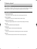
Operating Mechanism
• Controller operation
• Operator/gas burner/air supplier/ventilator operation
• Automatic operation of the controller
• Drying by the automatic sensor
1. Controller
• MAIN PCB
• FRONT PCB
• HARNESS
• POWER CORD ASS'Y :15A
4. Heat Exchanger & Dryer
• DRUM
• LIFTER
• Drying temperature sensor
5. FILTERING
• FILTER ASS'Y
6. Air-Ventilator
• Air-vent duct
3. Gas Burner
• Gas Valve AS(LNG, LPG)
• THERMOSTAT
2. Drive
• IMPELLER FAN
• MOTOR ASS'Y
• THERMOSTAT
• BELT/IDLER ASS'Y
Laundry
control pannel
lifter
plate top
Electric Input
Program
duct inlet
duct outlet
impeller fan
filter as
cabinet front
door
Summary of Contents for KUD-WG33S
Page 1: ...JUL 2008 Service Manual Model KUD WG33S Gas Dryer ...
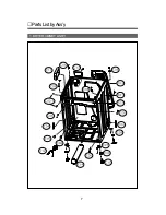
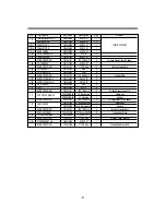
Page 8: ...1 DRYER CBINET ASS Y PartsListbyAss y 7 ...
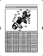
Page 35: ...33 2 DIAGRAMA SECADORA DE GAS ...
Page 58: ...57 BLOCK DE TERMINALES 1 Remove cover terminal 2 Remove 3 screws sólo secadora eléctrica ...
Page 63: ...4 Switch de Puerta Presione los seguros y empuje hacia el frente ...


