

4. Specification
For items not described in the above specification table, please contact our sales personnel.
5. External dimension
Supported couplings
For details, please contact our sales personnel.
Model
UTM
Ⅱ
-20Nm/UTM
Ⅱ
-20Nm(K)
Rated capacity
±20Nm
Power supply input
DC24V±15%
Consumption current
150mA or less
Signal output
±5V DC
Load resistance
2k
Ω
or more
Responsivity
1kHz
Pulse output
4pulses output/rotation
Open collector output
Rated DC30V 10mA
Signal delay
0.16ms (63.2% Response)
Safe overload
500%FS
Non-linearity
0.03%FS (Typ)
Hysteresis
0.03%FS (Typ)
Repeatability
0.03%FS (Typ)
Operation temp. range
-
10
~+
50
℃
Temperature effect on
zero
0.01%FS/
℃
(Typ)
Temperature effect on
span
0.01%FS/
℃
(Typ)
Maximum rotation speed
20000rpm
Weight (main body only)
Approx.700g
Torsional spring constant
5386Nm/rad
Maximum torsional angle
3.71×10
-3
rad
(0.213°)
Inertia moment
2.60×10
-5
kgm
2
Torsional natural
frequency (rotor section)
7.1kHz
Model
Supported couplings
UTM
Ⅱ
-20Nm/UTM
Ⅱ
-20Nm(K)
UCM44
UCM56
UCM65
.H\JURRYHRSWLRQ؟870⋜1P.
ٔ
ٔ
ٕ ٕ
0
5HPRYDOWDS
ٔ
ٕ
ٔ
ٕ
K
ٔ ٕ
Ǿ
K
Ǿ
K
Ǿ
ٔ ٕ
)RUr[LQJ
0'HSWK
$WWDFKHGFDEOHZLWKDFRQQHFWRU
Ǿ
FRUHVKLHOGHGFDEOHP
FDEOHHQGVHSDUDWHG
&RQQHF533
Unit
:
mm
6. About installation
Installation of couplings
For installation, make sure to use single flexible couplings. Never make rigid connections.
Never use with chains or belts applied directly to the shafts of this product.
Select couplings according to the purpose of use. Be careful not to exceed the maximum allowable load
during installation work.
How to install this product
This product can be used in either the horizontal or vertical direction. Also, there is no limit to the cable
drawing-out direction.
For installation to your equipment, float the housing of this product and provide a detent with rigid
polyurethane foam, double sided tape, etc., to such an extent that the housing will not turn. Do not fix the
housing/body of UTM rigidly (it may cause misalignment and thus affect measuring results adversely).
Checking after installation
・
After installation, check the output under low-speed rotation.
In the case of off-centering or angle deviation during installation, fluctuations appear with rotation;
therefore, installation should be adjusted so that required accuracy can be obtained.
・
To prevent vibration from occurring with rotation, adjust the dynamic balance of the whole equipment
according to the rotation speed used after installation.
Allowable installation errors
Perform installation with the accuracy at the following allowable installation errors or less.
If the recommended values of the couplings used are higher in requirements, they should be followed.
Rotation starting/stopping conditions and torque
At design-time and before operation, make sure that there is no possibility that the torque applied to this
product will exceed the rating when rotation is started or stopped.
Temperature gradient
Perform installation so as to prevent a temperature gradient from occurring between the shafts.
Perform installation so that heat will not be conducted directly to the shafts from other devices.
Heat generation
High-speed rotation of the shafts will cause the bearings to produce heat. Take cooling measures, such as
ventilation, as necessary.
870⋜
870⋜
Drive unit
Measuring object
Drive unit
Measuring object
Float the housing via bearings between the couplings
Drive
Load
Drive
Load
and other devices.
Bearing
Bearing
Bearing
Bearing
■
Allowable eccentricity: 3/100mm or less
■
Allowable off-centering: 3/100mm or less
■
Allowable deflection angle: coupling manufacturer's
■
Allowable variation between axial ends: 3/100mm or less
θ
recommended value or less
The temperature gradient is small.
A temperature gradient has occurred.
Hot
Cold
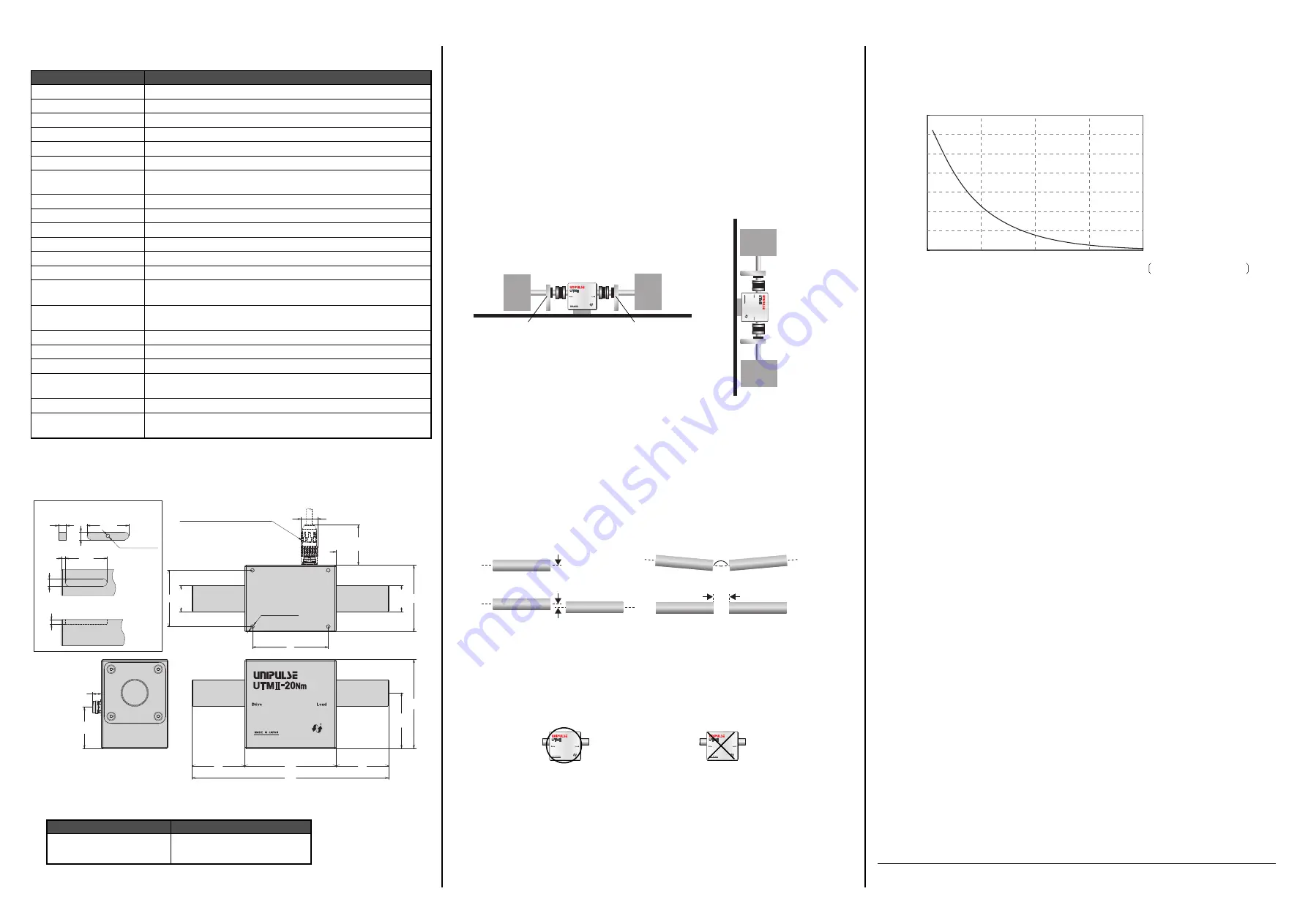
7. About the parts having a lifetime
This product reaches the end of its life by the wear of the bearings. The life by the wear of the bearings
greatly differs according to the use conditions, but it should be controlled by taking the following as a guide.
8. Troubleshooting
Q. No torque signal is output.
A.
1
)
Check the power supply voltage. Check to see if the power supply voltage is 24V DC.
2
)
Open the wiring except the power supply, apply torque, and measure the voltage between SIG OUT
and SIG GND.
・
If voltage is not output in this state, this product is assumed to be faulty.
・
If voltage is output in this state, the connection method is assumed to have a problem.
Since each GND of this product is internally common, check the method of connection with
external devices.
Q. A torque signal is output in spite of no load.
A.
Uninstall this product from the equipment, and bring the product alone into a no-load state.
In this state, if the output still exceeds the range expected from the specifications, this product is
assumed to be faulty. The zero point may be out of adjustment due to a sudden temperature change or
overload.
Check the specifications of the equipment to which this product has been installed and the operating
method for problems.
Q. The temperature of this product is abnormally high.
A.
The temperature rise under conditions in which the power is on and the shafts are not rotated is
approxi10
℃
from the ambient temperature.
Even when they are rotated, the temperature rise under conditions in which improper load is not applied
to the shafts is approxi20
℃
(20000rpm). When using at 10000rpm or more, we recommend that
you keep in mind the ambient temperature and cool the housing by ventilation etc.
If the temperature of this product is obviously abnormal compared with the above, the following causes
are assumed.
1
)
Check that heat is not conducted from any other heat source through the shafts.
2
)
Check that the power supply voltage is 24V DC±15%.
3
)
If the temperature is high in spite of normal power supply and no rotation, this product is assumed
to be faulty.
4
)
If the temperature rises abnormally with normal power supply and rotation, it is assumed that
improper load (radial or thrust load) may be applied to the shafts, or the life has expired due to the
wear of the bearings.
Q. The output fluctuates with rotation.
A.
Operate this product alone, and check the fluctuation of the output. If the shafts rotate in a jerking
manner or roughly, it is assumed that the life has expired due to the wear of the bearings.
If the output fluctuates with rotation under conditions in which this product is incorporated, check the
allowable installation errors. The output is assumed to fluctuate due to the deformation of the couplings,
the shaft of the measuring object, etc.
Q. The output is not stable with a fixed load applied state.
A.
・
Check the measuring object, this product, and the whole equipment for vibration.
・
Check to see if there is no strong alternating magnetic field in the vicinity and no constant change in
temperature.
・
Check to see if the shafts are not electrically charged and no leakage current flows through the shafts.
If the output is still not stable, this product is assumed to be faulty.
We offer optimum peripherals, such as couplings, according to your application/use. Please feel free to
contact us.
7LPH+
5RWDWLRQUSP
Bearing life (predicted value)
At 20000 rpm
Approx.4000 hours
9-11 Nihonbashi Hisamatsucho, Chuo-ku, Tokyo 103-0005
Tel. +81-3-3639-6120 Fax: +81-3-3639-6130
Unipulse Corporation


