14
1.8 Connecting Instruction of Analog Trunk Card and CID card
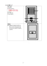
1.8.1 F9953 Two-ports of Trunk Card (TRK-2)
Description:
P1,P3 : Align P1, P9 of MPU card and
press the card down.
P2 : Connect to trunk line directly.
Pin 1,2 - CO1
Pin 3,4 - CO2.
GND: connect to GND of the MPU card.
Notice
:
Each system can only installed 1pc
of F9953.
It’s unnecessary to install the CID
card on ISDK-26 Plus KSU, unless
the metering pulse is needed.
F9953
Trunk Card
P1
P3
P2
GND
1
2
3
4
1.8.2 F9803C Four-ports of Trunk Card (TRK-4)
Description:
JP1, JP3 : Connect to JP3 & JP4 of MPU
card or JP2 & JP4 of another
expanding card by Ribbon cable.
JP2, JP4 : Connect to next expanding card
by Ribbon cable.
JP5 : Connect to trunk line directly.
Pin 1,2 - CO1; Pin 3,4 - CO2;
Pin 5,6- CO3; Pin 7,8 - CO4.
P3,P5 : Installed the Caller-ID card on.
GND: connect to GND of the MPU card.
LED: It will be ON/OFF repeating when
the card is working
F 9803
Trunk Card
UD-2150
Caller ID
L
E
D
LED
GND
JP
3
JP
4
P3
P5
JP
1
JP
2
12
34
56
78
JP5


