23
Continued set up of the Spool Gun with RAZORWED-MIG250MTS
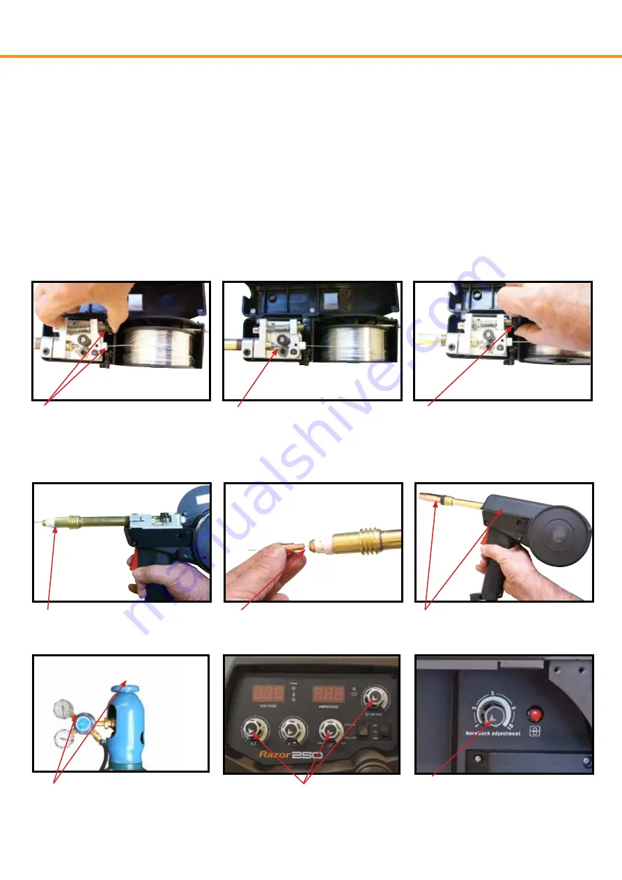
(9) Carefully feed the wire over the drive roller into the outlet guide tube, feed through into the torch neck.
Check that the drive roller being used complies with the wire diameter, replace the roller if necessary.
(10) Align the wire into the groove of the drive roller and release the tension arm making sure the wire is
in the groove of the drive roller.
(11) Apply a medium amount of pressure to the drive roller by winding in the tension adjusting knob.
(12) Remove the gas nozzle and contact tip from the torch neck, Pull the trigger to drive the wire through
the neck until it exits the contact tip holder
(13) Fit the correct sized contact tip and feed the wire through it, screw the contact tip into the tip holder of
the torch neck and nip it up tightly.
(14) Fit the gas nozzle to the torch head and close the wire spool cover.
(15) Carefully open the gas cylinder valve and set the flow rate to between 8-12 l/min.
(16) Set the welding parameters using the voltage, inductance and wire feed control knobs.
(17) Using the Burn Back control set the amount of wire to ‘burn back’ after you release the torch
trigger. This prevents the wire becoming stuck in the weld pool when finishing the weld.
(9) Carefully feed the wire through the inlet
guide tube onto the drive roller through into
the outlet guide tube. Squeezing the tension
arm adjustment knob to release the pressure
of the tension arm will allow the wire to be
guided through the drive roller easily
(10) Check to make sure that the wire
passes cleanly through the drive roller into
the outlet guide tube.
(13) Fit the contact tip over the wire and
screw it into the tip holder, nip it up tight.
(14) Fit the gas nozzle and close the wire feed
spool cover
(12) Remove the gas nozzle and contact tip.
Pull the trigger to drive the wire through the
neck until it exits the contact tip holder
(11) Apply a medium amount of pressure
using the tension arm adjustment knob.
(17) Adjust the burn back control to prevent
the wire sticking in the weld pool. Burn back
control is located above the wire feed motor
(16) Set welding parameters using
the voltage, inductance and wire feed
controls.
(15) Carefully open the valve of the gas
cylinder, set the flow to 8-12 l/min
Note: Pictures may vary from your model machine
Summary of Contents for KUMJRRW250
Page 50: ...51 ...


