


page 16
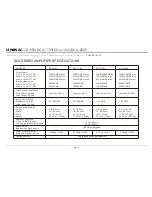
DCA-SERIES AMPLIFIER SPECIFICATIONS
MODEL NO.
DCA-900
DCA-1100
DCA-1300
Output Power:
2 ohms, 1 Khz 1% THD
4 ohms, 1 Khz 1% THD
8 ohms, 1 Khz 1% THD
(Bridge Mode, mono)
4 ohms, 1 Khz 1% THD
8 ohms, 1 Khz 1% THD
320W RMS Stereo.
270W RMS Stereo.
180W RMS Stereo.
640W RMS
540W RMS
620W RMS Stereo.
440W RMS Stereo.
260W RMS Stereo.
1240W RMS
880W RMS
1000W RMS Stereo.
700W RMS Stereo.
420W RMS Stereo.
2000W RMS
1400W RMS
Total Harmonic Distortion
20Hz-20kHz, @ rated
output power, 8 ohms
Less than 0.01%
Input Sensitivity and
Impedance: @ rated
output power, 8 ohms
0.775V RMS
0.775V RMS
1.0 V RMS
3.5" (8.8cm)
19" (48.3cm)
16.14" (41cm)
24.64 lbs. (11.2kg)
3.5" (8.8cm)
19" (48.3cm)
16.14" (41cm)
31.46 lbs. (14.3kg)
3.5" (8.8cm)
19" (48.3cm)
16.14" (41cm)
37.4 lbs. (17kg)
Dimensions & Weight:
Height
Width
Depth
Weight
Frequency Response:
+/- 1db, 1w RMS. 8 ohms
+/- 0.2 db, @ rated output, 8 ohms
10 Hz - 40 kHz
20 Hz - 20 kHz
Hum & Noise:
Below rated output,8 ohms
100 dB, unweighted
Power Consumption: @
rated output power, 8 ohms
4.28A @ 110VAC
5.63A @ 110VAC
9.1A @ 110VAC
Cooling System:
Dual Speed Fans and Heatsinks
Less than 0.02%
Less than 0.01%
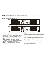
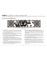
UNiKA
DCA-900/DCA-1100/DCA-1300/DCA-2000
DCA-2000
1200W RMS Stereo.
1000W RMS Stereo.
620W RMS Stereo.
2400W RMS
2000W RMS
1.0 V RMS
3.5" (13.3cm)
19" (48.3cm)
17.08" (43.4cm)
55.66 lbs. (25.3kg)
12.54A @ 110VAC
Less than 0.025%
Introduction Front Panel Rear Panel Set Up Operating Modes Protection Features
Specifications


