background image

unigreen  

9

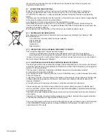
4.1.2 HAND WASHING TANKS

The mistblowers are supplied with an auxiliary hand-washing tank with clean
water and a hand tap.
This tank must always be supplied with water and the inside must be clean so
you can wash any parts of the body that come into contact with the chemical
product used.
Never drink the liquid inside.

4.2

PRELIMINARY CHECKS

When you receive the machine, check that it is complete and no parts are
missing.
If there are any damaged parts, inform your local reseller or UNIGREEN
directly in good time.
When the machine is delivered, make sure you ask:

a)

that the machine is delivered with all of its parts fitted and that the fitting

meets the requisites in table N° 17a (pages  34).
This procedure is necessary because for reasons of space during
transportation the machine is often delivered partially dismantled.

b)

that it is tested in your presence in particular checking:

=

that the suction filter and the inside of the tank are clean and free of work

residues.

=

that the connections are made correctly following the basic layout (FIG. N°

16, page 16).

=

that the hose clips and all the unions and connections are tightened

properly.

=

that all of the protective covers are fitted solidly to the machine, in

particular the protective cover of the power-takeoff of the pump.

=

that the multiplier is sufficiently supplied with lubricant oil.

=

that the zone where the fan turns hasn’t been bent by knocks during

transportation.

4.3

TRANSPORTING AND MOVING THE MACHINE

Every time you have to lift the machine, before starting the operation, always
make sure the lifting gear and the relevant tools and equipment (cables, hooks,
etc..) are suitable for lifting the load and check the stability of the same.

It is forbidden to unhook and move the machine with the tank full.

The dry weight of the machine at the maximum level of fitting and with all the
accessories allowed is stamped on the nameplate (FIG.2); use slings and
lifting gear with a adequate load-bearing capacity (FIG.3).
Never lift or move the mistblowers by hand if there is liquid in the tank. The
machine will weigh more and the movement of the liquid can change the centre
of gravity causing uncontrolled movements.
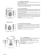
We recommend using slings as shown in the figure, the lifting points to use on
the machine are indicated with the relevant symbol.
Don’t lift the machine with the forks of a forklift truck because the machine can
tip over due to the overhanging weight of the blower group.
Don’t pass or stand under the machine when it is being lifted.

4.3.1 MOUNTED ATOMISERS

PARKING
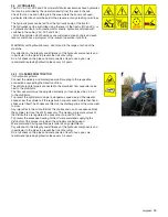
Don’t stand the atomiser on unstable ground or steep slopes, the machine is
designed to be parked safely on compact ground with a slope of up to 8.5°

MOVING
To lift the machine, follow the instructions above.

Questo simbolo identifica la
cisterna di acqua pulita ad uso
lavamani presente sulla macchina

Questo simbolo
identifica i punti di
aggancio della
macchina

FIG.3

Movimentare e sollevare la macchina
solo con cisterna vuota

Summary of Contents for TurboTeuton P300

Page 1: ...04 2010 USE AND MAINTENANCE MANUAL MISTBLOWERS TURBOTEUTON MOUNTED MISTBLOWERS serie TURBOTEUTON MAIA TT P Polipo P SuperSpalliera RV GDV Read this manual carefully before use GB ...

Page 2: ...ANSPORTING AND MOVING THE MACHINE 9 4 3 1 MOUNTED ATOMISERS 9 4 4 TRACTOR COUPLING 10 4 4 1 THREE POINT COUPLING 10 4 4 5 HYDRAULIC CONNECTION TO THE DISTRIBUTORS 10 4 5 CARDAN SHAFT 11 4 6 PUMP 11 4 7 SUCTION FILTER 11 4 8 PRESSURE REGULATOR 12 4 8 1 COMPONENTS OF THE PRESSURE REGULATOR 12 4 8 2 GENERAL INSTRUCTIONS 12 4 8 3 DELIVERY FILTERS ONLY EQUIPPED MODELS 13 4 9 AUXILIARIES TAPS BLOCK 13 4...

Page 3: ...ING POLIPO 4 4 8 NOZZLES NARROW ROWS 26 TABLES FOR CALIBRATING POLIPO 4 4 16 NOZZLES NARROW ROWS 26 TABLES FOR CALIBRATING POLIPO 4 4 8 NOZZLES WIDE ROWS OPTIONAL 27 TABLES FOR CALIBRATING POLIPO 4 4 16 NOZZLES WIDE ROWS OPTIONAL 27 TABLES FOR CALIBRATING POLIPO 5 5 20 NOZZLES NARROW ROWS 28 TABLES FOR CALIBRATING POLIPO 5 5 10 NOZZLES NARROW ROWS 28 TABLES FOR CALIBRATING POLIPO 5 5 10 NOZZLES WI...

Page 4: ... work speed over that indicated in the spraying tables in the handbook or too high for the conditions of the terrain use of herbicide booms without an auto levelling system or with the auto levelling system blocked power takeoff speed over 540 rpm Mounted mistblowers activation of the three point elevator with cardan shaft engaged and power takeoff operational And anything else indicated in the pr...

Page 5: ... with the improper use of the machine by the operator for this purpose danger signs and symbols and prohibitions are applied near some parts of the machine see previous pictograms Key to the symbols 1 Read the Use and Maintenance manual 2 Stop the machine and read the manual before every intervention 3 Don t lubricate while running 4 Don t drink 5 Don t dispose of residue liquids in the environmen...

Page 6: ...ase only after having carefully read the instructions on the container 2 3 1 REGULATIONS FOR THE USE OF CHEMICAL PRODUCTS Some recommendations for avoiding damage and accidents Keep the machine in a suitable protected place with no access for children or strangers Handle the products with care wearing rubber acid proof gloves goggles face masks or filtering helmets overalls made of water repellent...

Page 7: ...hese machines are identified by the word washing on the CE plate 2 7 DRIVING ON THE ROAD The towed mistblowers are not specifically designed for road use Nevertheless many models are also available in the version homologated for road traffic with the tank empty You should check with your local reseller on the correct couplings to use and use tractors that meet the regulations in force 3 CHARACTERI...

Page 8: ...r components for hydraulic and pneumatic transmissions Hydraulics UNI EN ISO 4254 1 June 2006 Agricultural machines Safety Part 1 General requisites ISO 11684 1995 Pictograms general principles 4 INSTRUCTIONS To use the machine the personnel must be suitably trained on the basis of the regulations in force on safety and hygiene at work THE USE OF THE MACHINE FOR PERSONS UNDER 18 YEARS OF AGE IS ST...

Page 9: ...hasn t been bent by knocks during transportation 4 3 TRANSPORTING AND MOVING THE MACHINE Every time you have to lift the machine before starting the operation always make sure the lifting gear and the relevant tools and equipment cables hooks etc are suitable for lifting the load and check the stability of the same It is forbidden to unhook and move the machine with the tank full The dry weight of...

Page 10: ...f the elevator coupling pins If necessary position the double diameter pins correctly there are also appropriate adapter bushes available c Adjust the length of the third point tie rod correctly so the sprayer is perfectly vertical in normal working position d Check for the presence of the safety pins that stop the arms of the tractor jumping off the connecting pins 4 4 5 HYDRAULIC CONNECTION TO T...

Page 11: ...f the pump FIG 7 NEVER USE THE CARDAN TRANSMISSION IF THE FOLLOWING PROTECTIVE COVERS ARE MISSING TRACTOR POWER TAKEOFF PROTECTIVE COVER CARDAN SHAFT PROTECTIVE COVER FIXED PROTECTIVE COVER ON THE PUMP SHAFT 4 6 PUMP When using the pump scrupulously observe the instructions in the enclosed handbook supplied by the manufacturer The pump can be identified by the ratings plate on the same the main da...

Page 12: ...tion regulator G D auxiliary tap can be used for various accessories it is always manual E volumetric pressure valve proportional when present it regulates the spraying pressure The valve automatically compensates variations in speed within the scope of the same gear ratio keeping the quantity of liquid supplied per surface unit litres hectare unchanged F self cleaning filter filters the delivery ...

Page 13: ...adjust the corresponding compensator G until you return to the pressure set previously displayed on the manometer open and close the tap of section C and check that the pressure remains constant repeat the above operations for all the section taps If the types of nozzles aren t changed the regulations carried out will guarantee a constant spraying of the liquid also per treatments that are done at...

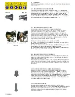
Page 14: ... and after filling stop the pump and put the lever of deviator D back in the working position disconnect pipe T from deviator D b FILLING WITH THE SUCTION FILTER Fig 3 Fig 11 If the 3 way deviator isn t fitted you can fill the tank using the coupling on the cover of the suction filter Unscrew the rear wing nut of the filter and using a G1 1 2 threaded union connect pipe T with the floating filter ...

Page 15: ...w for using chemical products are indicated in paragraph 2 2 1 4 12 2PREMIXER ON COVER OPTIONAL Open the cover and pour all of the chemical powder into the filter close the cover and open the supply tap until all of the powder has dissolved 4 12 2PREMIXER ON COVER OPTIONAL Open the cover and pour all of the chemical powder into the filter close the cover and open the supply tap until all of the po...

Page 16: ... the power takeoff b Check you have filled the circuit washer tank C c Make sure the main control of the pressure regulator is OFF and that all the boom sectors are closed d Turn suction deviator A to the circuit washer position H2O e Start the diaphragm pump by engaging the power takeoff f Increase the engine speed until all of the liquid in circuit washer tank C has been sucked up g Turn the dia...

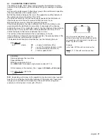
Page 17: ...e to engage the fan rotor gradually This prevents jerky starts due to the inertia of the fan rotor which can have a negative effect on the transmission For the centrifugal clutch to work properly the speed of the power takeoff mustn t be less than 450 rpm especially if you are using the first gear of the multiplier Generally clutches with shoes plates made of sintered material with a high coeffici...

Page 18: ... way for the configuration of the vegetation All the adjustments are made by hand using knobs and screws When treating particularly wide rows up to 4 m OPTIONAL extendable arms are available The POLIPO accessory is used with STD version fans 5 3 2 SUPER SPALLIERA FOR ESPALIER With this accessory you can treat particular espaliers with thick vegetation It is especially indicated where you need to p...

Page 19: ... 4 1 OIL FEED FROM TRACTOR for hydraulic systems Connect the delivery and discharge quick fit coupling to the respective connections respecting the direction of flow The distributor inlet pipe is connected to the aluminium flow separator valve next to the distributor The flow separator must be adjusted correctly so it sends less than 4 5 L 1 to the distributor To prevent the cylinders moving at a ...

Page 20: ...or the single jet if it is facing inwards towards the blower group c nozzle second spray when these are pointing towards the outside of the blower group parallel with the non drip valve 6 2 DESCRIPTION OF TYPE OF NOZZLES The nozzles are extremely important to obtain a correct distribution on the vegetation to be treated Poor quality or worn nozzles have a tendency to create unevenly treated strips...

Page 21: ...he 5 m rows The last line of the table indicates the overall delivery of the fan If the mistblower is fitted with non standard nozzles the spraying tables of the single nozzles per mistblower are on page 32 To calculate the distribution in litres hectare use the following formula Vd 600 x Q I x V where Vd volume to distribute L ha Q sum of the nozzles delivery L min I distance between the rows m V...

Page 22: ...are indicated in paragraph 2 2 1 8 1 PROGRAMMED MAINTENANCE TAB N 7 page 33 We recommend using a table of programmed maintenance to follow in time to keep the mistblower in an efficient working condition For major and important maintenance jobs we recommend using the normal UNIGREEN assistance service available from your reseller if necessary replacing parts using original spare parts only 8 2 ROU...

Page 23: ...ble from our reseller perform any repairs or contact a specialised workshop During all of the repairs in particular when welding the machine and the circuit must be clean of any residues of chemical product If the machine has to be lifted for example to change a wheel follow the instructions in point 4 3 of the present handbook Also make sure the machine is stopped connected to the tractor and use...

Page 24: ...rt and disposal recovery Transport of one s waste to authorised collection centres is allowed exclusively if you are enrolled in the Environmental Management Register 8 7 3 ELECTRICAL AND ELECTRONIC APPARATUS WASTE EEAW The Italian government has adopted the European Parliament directives in the matter of the disposal of electrical and electronic waste EEAW 2002 95 CE and 2003 108 CE Directives wi...

Page 25: ... B1606 0015 filter for Ø18 jet holes Ø 0 8 1002 0110F Ceramic conical nozzle kit Nozzle Ø0 8 Dif Ø1 0 Filter Ø0 8 3400 0400F filter diffuser and seal Nozzle Ø1 0 Dif Ø1 0 Filter Ø0 8 3400 0401F for Ø18 mm jet Nozzle Ø1 2 Dif Ø1 2 Filter Ø1 0 3400 0402F Nozzle Ø1 5 Dif Ø1 5 Filter Ø1 0 3400 0403F Nozzle Ø1 8 Dif Ø1 8 Filter Ø1 0 3400 0404F Nozzle Ø2 0 Dif Ø1 8 Filter Ø1 0 3400 0405F Clamp kit for f...

Page 26: ...on 8 getti Lt ha spreading rate table for Turbo Teuton 8 NOZZLES ISO ARANCIO Orange ISO GIALLO Yellow Larghezza di lavoro PRESSIONE bar 5 7 10 12 15 18 20 5 7 10 12 15 18 20 working width 3 5 390 457 552 590 667 733 771 771 905 1086 1190 1324 1448 1533 4 342 400 483 517 583 642 675 675 792 950 1042 1158 1267 1342 5 273 320 387 413 467 513 540 540 633 760 833 927 1013 1073 1 8 6 228 267 322 344 389...

Page 27: ...ti Lt ha spreading rate table for Turbo Teuton 8 NOZZLES ISO ARANCIO Orange ISO GIALLO Yellow Larghezza di lavoro PRESSIONE bar 5 7 10 12 15 18 20 5 7 10 12 15 18 20 working width 3 5 281 329 398 425 480 528 555 555 651 782 857 953 1042 1104 4 246 288 348 372 420 462 486 486 570 684 750 834 912 966 5 197 230 278 298 336 370 389 389 456 547 600 667 730 773 2 5 6 164 192 232 248 280 308 324 324 380 ...

Page 28: ...euton 10 getti Lt ha spreading rate table for Turbo Teuton 10 NOZZLES ISO ARANCIO Orange ISO GIALLO Yellow Larghezza di lavoro PRESSIONE bar 5 7 10 12 15 18 20 5 7 10 12 15 18 20 working width 3 5 486 571 686 743 838 914 962 962 1133 1352 1486 1657 1810 1914 4 425 500 600 650 733 800 842 842 992 1183 1300 1450 1583 1675 5 340 400 480 520 587 640 673 673 793 947 1040 1160 1267 1340 1 8 6 283 333 40...

Page 29: ...ti Lt ha spreading rate table for Turbo Teuton 10 NOZZLES ISO ARANCIO Orange ISO GIALLO Yellow Larghezza di lavoro PRESSIONE bar 5 7 10 12 15 18 20 5 7 10 12 15 18 20 working width 3 5 350 411 494 535 603 658 693 693 816 974 1070 1193 1303 1378 4 306 360 432 468 528 576 606 606 714 852 936 1044 1140 1206 5 245 288 346 374 422 461 485 485 571 682 749 835 912 965 2 5 6 204 240 288 312 352 384 404 40...

Page 30: ...ton 10 getti Lt ha spreading rate table for Turbo Teuton 10 NOZZLES ISO ARANCIO Orange ISO GIALLO Yellow Larghezza di lavoro PRESSIONE bar 5 7 10 12 15 18 20 5 7 10 12 15 18 20 working width 3 5 350 411 494 535 603 658 693 693 816 974 1070 1193 1303 1378 4 306 360 432 468 528 576 606 606 714 852 936 1044 1140 1206 5 245 288 346 374 422 461 485 485 571 682 749 835 912 965 2 5 6 204 240 288 312 352 ...

Page 31: ...Turbo Teuton GDC 10 getti Lt ha spreading rate table for Turbo Teuton GDC 10 NOZZLES ISO ARANCIO Orange ISO GIALLO Yellow Larghezza di lavoro PRESSIONE bar 5 7 10 12 15 18 20 5 7 10 12 15 18 20 working width 3 5 350 411 494 535 603 658 693 693 816 974 1070 1193 1303 1378 4 306 360 432 468 528 576 606 606 714 852 936 1044 1140 1206 5 245 288 346 374 422 461 485 485 571 682 749 835 912 965 2 5 6 204...

Page 32: ...SSURE BAR JET CAPACITY Lt min 5 cone 1 16 1 40 1 90 2 25 2 65 2 90 3 50 direct jet 1 40 1 70 2 50 3 95 4 7 6 00 7 70 8 cone 1 40 1 80 2 60 2 80 3 40 3 65 4 45 direct jet 1 70 2 20 3 40 4 85 6 00 7 60 9 80 10 cone 1 50 1 96 2 90 3 10 3 90 4 10 5 00 direct jet 1 90 2 40 3 75 5 40 6 95 8 55 11 0 15 cone 1 88 2 40 3 40 3 80 4 50 5 00 6 10 direct jet 2 30 3 00 4 50 6 65 8 30 10 4 13 4 30 cone 2 60 3 40...

Page 33: ...on the lever correctly Command group isn t at zero pressure Valves and or valve seats Replace or clean suction and delivery worn or dirty The pump doesn t reach the set Valve and or valve seat Replace pressure adjustment worn Valves and or valve seats suction Replace or clean and delivery worn or dirty Insufficient rpm Bring speed up to correct rpm always in the field of 350 550 rpm The nozzles us...

Page 34: ...R GCP 2 ELECTRIC PRES X X X X DISTRIBUTOR POLIPO 4 4 X X X X ACCESSORIES POLIPO 5 5 X X X X SUPER SPALLIERA 4 4 X X X X RV GDC 5 5 X X X SINGLE Ø18 X X X X NOZZLES DOUBLE Ø18 X X X X NOZZLE TIPS Ceramic CONE X X X X CIRCUIT WASHING DEVICE X X X X OPTIONALS EJECTOR X X X X MIXER LP83 X X X X WHEELS KIT X X X X EXTENDABLE ARMS X X X X TOTAL MASS EMPTY MAX FITINGS 295 430 440 450 in Kg FULL MAX FITIN...

Page 35: ...unigreen 35 ...

Page 36: ...serves the right to make variations or modifications without prior warning via Rinaldi 105 42124 Reggio Emilia ITALY Tel 39 0522 369811 Fax 39 0522 369898 e mail info unigreen spa com internet www unigreen spa com member of the group UNI 16100021F GB Apr 10 ...

Reviews: