PART III: OPERATION
21
ADJUSTING AIR AND FUEL FLOW RATES
Adjusting air and gas flow rates
Adjustments - brief description
The air and fuel rates adjustments must be performed at the maximum ouptput first (“high flame”): see the LMV5.. related manual..
Check that the combustion parameters are in the suggested limits.
Then, adjust the combustion values by setting the “fuel/air” ratio” curvepoints (see the LMV5.. related manual).
Set, now, the low flame output, in order to avoid the low flame output increasing too much or that the flues temperature gets too low
to cause condensation in the chimney.
Adjusting procedure
Go on adjusting the burner.
Users can set only the LMV parameters that can be accessed without password: (see “Adjusting the temperature set-point”).
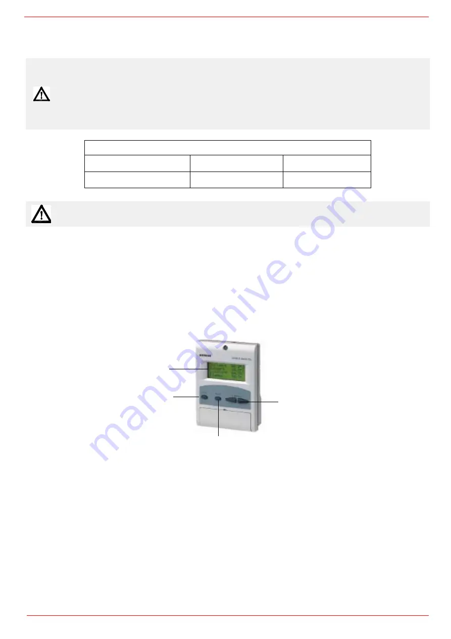
The Siemens AZL User Interface allows programming the Siemens LMV system and monitoring the system data.
The user interface is made of:
1. display: it showes menus and parameters
2. ESC key (previous level): it goes back to the prevoius level menu or exits the programming mode without changing data.
3. ENTER key (next level): it confirms the data changing and jumps to the next menu/parameter.
4. SELECT keys: they select a menu item and change the parameter values.
As far as the settings, see the LMV5 related manual.
By following the “air/gas ratio” curvepoints setting procedure on the LMV5.. manual, adjusting the air and gas flow rates: check, conti-
nuosly, the flue gas analisys, as to avoid combustion with little air; dose the air according to the gas flow rate change following the steps
quoted below.
Once the throttle valve is completely opened, acting on the pressure stabiliser of the valves group, adjust the
gas flow rate in the high
flame stage
as to meet the values requested by the boiler/utilisation:
WARNING! During commissioning operations, do not let the burner operate with insufficient air flow (danger of
formation of carbon monoxide); if this should happen, make the fuel decrease slowly until the normal
combustion values are achieved.
WARNING: any changes to the burner setting (intervention on the combustion head, air register, leverages,
components for adjusting the flow rate, etc.) must be performed by qualified personnel, checking the
combustion parameters by flue gas analyzer. This applies to all operations described in the following
paragraphs.
WARNING! the combustion air excess must be adjusted according to the values in the following chart.
Recommended combustion parameters
Fuel
Recommended (%) CO
2
Recommended (%) O
2
Natural gas
9 ÷ 10
3 ÷ 4,8
ATTENTION: THE BURNED GAS RATE MUST BE READ AT THE GAS FLOW METER.
1
2
3
4
Summary of Contents for URB40
Page 37: ......
Page 38: ......
Page 39: ......
Page 42: ...Annex1 Example for motor cable...
Page 43: ......
Page 44: ...Annex 2 Example for sensor cable...
Page 45: ......
Page 46: ......
Page 50: ......


