


10
Electrical connections
To execute the electrical connections, proceed as follows:
1
remove the cover from the electrical board, unscrewing the fixing screws;
2
execute the electrical connections to the supply terminal board as shown in the following diagrams,
3
check the direction of the motor (see next pargraph)
4
refit the panel cover
WARNING:
The burner is provided with an electrical bridge between terminals 6 and 7; when connecting the high/low flame
thermostat, remove this bridge before connecting the thermostat.
IMPORTANT:
Connecting electrical supply wires to the burner teminal block MA, be sure that the ground wire is longer than
phase and neutral ones.
auxiliary contacts are provided (terminals no. 507 and no. 508 of the MA terminal block) to connect an intervention system
(alarm/power supply cutoff) in case of fault of the oil resistor contactor (see Fig. 1-Fig. 2).
Respect the basic safety rules. Make sure of the connection to the earthing system. do not reverse the phase and neutral
connections. Fit a differential thermal magnet switch adequate for connection to the mains.
ATTENTION:
before executing the electrical connections, pay attention to turn the plant’s switch to OFF and be sure that the
burner’s main switch is in 0 position (OFF) too. Read carefully the chapter “WARNINGS”, and the “Electrical connections”
section.
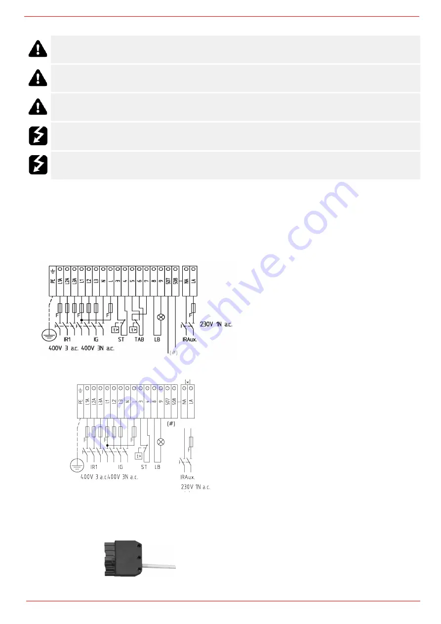
Fig. 1
-
Progressive burners
Fig. 2 - Fully modulating burners
(#) Free contact for ”Faulty heater resistor contactor”
Fig. 3
Probes connection oby means of the 7-pins plug (Fig. 4) - see Fig. 3) for
connections.
Fig. 4
7-pole manifold, see fig. 4. For connections, see attached
wiring diagram
MA
MA
Summary of Contents for RN510
Page 39: ......
Page 54: ......
Page 63: ......
Page 64: ......
Page 65: ...RWF50 2x RWF50 3x User manual M12922CB Rel 1 0 07 2012...
Page 80: ...16 Note Specifications and data subject to change Errors and omissions excepted...
Page 81: ...KM3 Modulator USER MANUAL M12927CA Rel 1 0 10 2020...
Page 82: ...M12927CA MOUNTING 2...
Page 98: ...1 RWF55 5X RWF55 6X User manual M12926CA Rel 0 1 10 2015...
Page 99: ...2 DEVICE INSTALLATION Fixing system Drilling dimensions...
Page 120: ......
Page 121: ...23 Note Specifications and data subject to change Errors and omissions excepted...
Page 130: ...OFF...
Page 131: ......
Page 132: ......
Page 133: ......
Page 134: ......
Page 135: ......
Page 136: ......
Page 137: ......
Page 138: ......