General unit data
Mains voltage
AC 230 V +10 % / -15 %
AC 120 V +10 % / -15 %
Mains frequency
50...60 Hz ±6 %
External primary fuse (Si)
6.3A (slow)
Power consumption
12 VA
Mounting orientation
optional
Weight
approx. 200 g
Degree of protection
IP40 (to be ensured through mounting)
Perm. cable lengths
max. 3m at line capacitance of 100 pF/m
Detector cable laid separately
10 m
Remote reset laid separately
20m
LMO14
LMO24
LMO44
Terminal 1
5 A
5 A
5 A
Terminals 3 and 8
3 A
5 A
5 A
Terminals 4, 5 and 10
1 A
1 A
1A
Terminals 6
1 A
1 A
2A
Flame supervision with QRB and QRC
QRB
QRC
Min. detector current required (with flame)
45 µA
70 µA
Min detector current permitted (without flame)
5.5 µA 5.5 µA
Max. possible with flame (tipically)
100 µA 100 µA
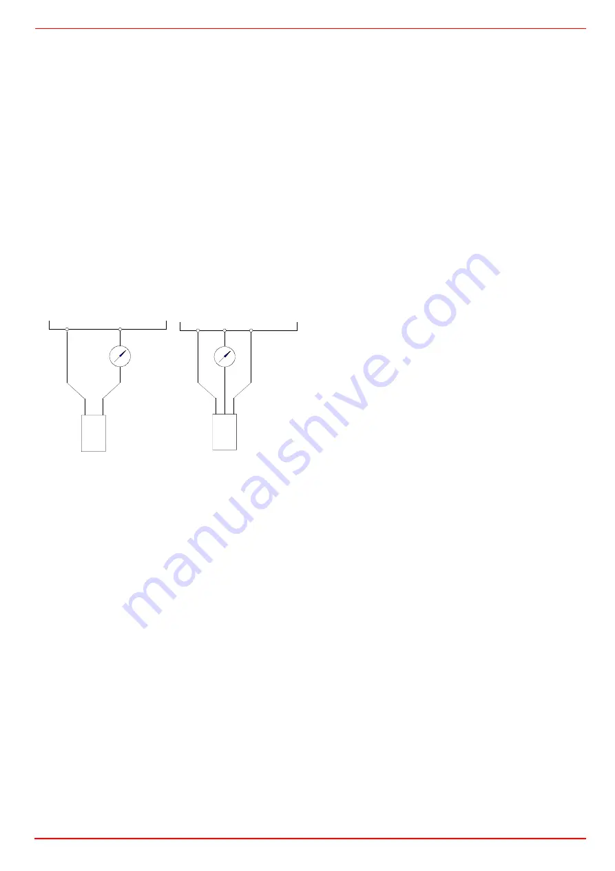
Measurement circuit for detector current
Key
µA DC
DC microamperometer with an internal
resistance of 5 k
max.
bl
Blue
sw
Black
br
Brown
LAL.. CONTROL BOX FOR OIL BURNERS
Use
Control and supervision of oil atomization burners
For burners of medium to high capacity
For intermittent operation (at least one controlled shutdown every 24
hours)
Universally applicable for multistage or modulating burners
Housing and plug-in base
Made of impact-proof and heat-resistance black plastic
Lockout reset button with viewing window; located behind it:
Lockout warning lamp
Lockout indicator coupled to the spindle of the sequence switch and
visible in the transparent lockout reset button
uses easy-to-remember symbols to indicate the type of fault and the
point in time lockout occurred
Base and plug-in section of the LAL... are designed such that only burner
controls of the LAL... family can be plugged in.
24 connection terminals
Auxiliary terminals «31» and «32»
3 earth terminals terminating in a lug for earthing the burner
3 neutral conductor terminals prewired to terminal 2
14 knockout holes for cable entry by means of cable glands
8 at the side
6 in the bottom of the base
6 lateral threaded knockout holes for cable entry glands Pg11 or M20
Operation
Flame detector and flame simulation test are made automatically during
burner off times and the prepurge time «t1». If loss of flame occurs during
operation, the burner control will initiate lockout. If automatic repetition of
the startup sequence is required, the clearly marked wire link on the plug-
in section of the LAL... must be cut away.
Pre-conditions for burner startup
Burner control is not in the lockout position
Sequence switch is in its start position (with LAL2 voltage is present at
terminals 11 and 12.
Air damper is closed; end switch «z» for the CLOSED position must
feed power from terminal 11 to terminal8.
Contact of the limit thermostat or pressure switch «W» and the con-
tacts of any other switching devices in the control loop between termi-
nals 4 and 5 must be closed e.g. a control contact for the oil
preheater’s temperature
Normally closed contact of the air pressure switch must be closed.
Startup sequence
Start command by «R»:
«R» closes the start control loop between terminals 4 and 5
The sequence switch starts to run
Only prepurging, fan motor at terminal 6 receives power
Pre- and postpurging, fan motor or flue gas fan at terminal 7 receives
power on completion of «t7»
On completion of «t16», the control command for opening the air dam-
per is delivered via terminal 9
Terminal 8 receives no power during the positioning time
The sequence switch continues to run only after the air damper has
fully closed.
t1
Prepurge time with air damper fully open:
The correct functioning of the flame supervision circuit is checked
during «t1»
The burner control will initiate lockout if correct functioning is not ensu-
red.
With LAL2:
Shortly after the beginning of «t1», the air pressure switch must change
over from terminal 13 to terminal 14 otherwise, the burner control will ini-
tiate lockout start of the air pressure check.
t3
Short preignition time:
«Z» must be connected to terminal 16, release of fuel via terminal 18.
12
11
LMO...
bl
µA DC
+
QRB...
7130v01/0700
sw
12
11
LMO...
1
sw
bl
br
µA DC
+
QRC1...
7130v02/0700


