background image

C.I.B. UNIGAS - M039121CE

23

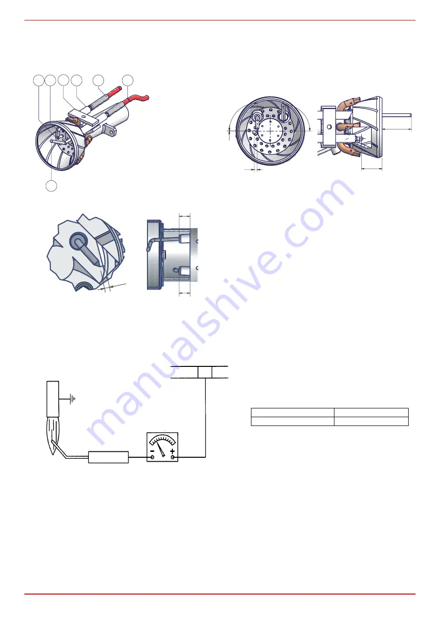
Correct electrodes positioning

To guarantee a proper ignition, the measures indicated in  must be respected.

Ensure the locking screw 

VE

 of the electrodes group is tight before refit the burner.

Fig. 15

Checking the detection current

If the burner locks, execute the following inpesctions. To measure the detection signals refer to the diagrams below. If the signal is less
than the value shown, check the position of the detection electrode, the electrical contacts and if necessary replace the detection
electrode. 

Seasonal stop

To stop the burner in the seasonal stop, proceed as follows:

1

turn the burner’s main switch to 0 (Off position)

2

disconnect the power mains

3

close the fuel cock of the supply line

Burner disposal

In case of disposal, follow the instructions according to the laws in force in your country about the “Disposal of materials”.

z

Standard burners (mm)

z

Low NOx burners  (mm)

Fig. 16

3

5

4

2

3

1

6

1

detection electrode

2

grounded electrode

3

ignition electrode

4

electrode fixing

5

ignition cable

6

detection cable

90

°

0

3

90°

28

20

2.5

10

10

Connector

 µA DC SCALE

2

Detection electrode

Flame

Control box

Minimum detection signal

Siemens LME11

3 µA

Summary of Contents for LG35

Page 1: ...M039121CE Rev 4 04 2009 BURNERS BRUCIATORI BRULERS BRENNER QUEMADORES ГОРЕЛКИ IDEA Series Gas burners MANUAL OF INSTALLATION USE MAINTENANCE LG NG NGX35 ...

Page 2: ... Gas MULTIBLOC control and safety group DUNGS MBC 65 DLE 16 Setting the startup gas flow rate 16 Setting the gas flow rate 16 Adjusting the maximum flow rate valve 16 Gas Valves Group DUNGS MB DLE 405 1 2 gas train burners 17 Adjusting the air flow rate 18 Adjusting the air and gas pressure switches 18 Calibration of air pressure switch only for single stage burners 18 Calibration of minimum gas p...

Page 3: ...ains electricity gas oil or other fuel z Observe caution with hot burner components These are usually near to the flame and the fuel pre heating system they become hot during the unit operation and will remain hot for some time after the burner has stopped When the decision is made to discontinue the use of the burner the user shall have qualified personnel carry out the following operations a Rem...

Page 4: ...of toxic or explosive mixtures DIRECTIVES AND STANDARDS Gas burners European directives Directive 90 396 CEE Gas Appliances Directive 2006 95 EC on low voltage Directive 2004 108 CEE on electromagnetic compatibility Harmonised standards UNI EN 676 Gas Burners CEI EN 60335 1 Household and similar electrical appliances Safety Part 1 General requirements EN 50165 Electrical equipment of non electric ...

Page 5: ... the comburent air without removing the burner cover All components can be fitted into a backing plate which can be easily moved and attached to special fixings within the burner to make maintenance easier Fig 1 Keys 1 Control box 2 Combustion head inside 3 Omponents plate 4 Air pressure switch The gas coming from the supply line passes through the valves group provided with filter and stabiliser ...

Page 6: ...o know the available gas pressure value upstream the burner gas valve Then subtract the backpressure The result is called pgas Draw a vertical line matching the furnace input value 600kW in the example quoted on the x axis as far as intercepitng the network pressure curve according to the installed gas train DN65 in the example From the intercep tion point draw an horizontal line as far as matchin...

Page 7: ...xt paragraph I3B P see next paragraph Gas rate min max Stm3 h 2 1 4 3 0 8 1 6 2 9 4 3 Gas pressure min max mbar Note2 65 Power supply 230V 1N ac 50 Hz Total power consumption W 380 Electric motor W 75 Protection IP40 Approx weight kg 12 5 Valves size Gas connection 3 8 Rp1 2 Operation Single stage Operating temperature C 10 50 Storage Temperature C 20 60 Working service Intermittent BURNERS NG35 M...

Page 8: ...to Stm3 h 1013 mbar pressure 15 C temperature and are valid for G20 gas nett calorific value Hi 34 02 MJ Stm3 for L P G nett calorific value Hi 93 5 MJ Stm3 Note2 Maximum gas pressure 65mbar with Rp3 8 Rp1 2 and Dungs MBC065DLE valves 360mbar with Rp1 2 and Dungs MB DLE 405 valves Minimum gas pressure see gas curves GAS CATEGORY COUNTRY I2H AT ES GR SE FI IE HU IS NO CZ DK GB IT PT CY EE LV SI MT ...

Page 9: ...86 162 194 M8 155 86 138 110 277 322 109 154 168 27 400 275 Ø78 5 NG35 L 1 2 416 34 156 260 383 269 14 255 Ø80 Ø95 86 162 194 M8 155 86 138 110 277 400 109 232 168 27 400 275 Ø78 5 NGX35 S 1 2 338 58 98 240 280 269 14 255 Ø80 Ø95 86 145 194 M8 153 96 120 108 257 297 89 129 168 7 400 266 Ø80 NGX35 L 1 2 338 58 178 160 280 269 14 255 Ø80 Ø95 86 145 194 M8 153 96 120 108 257 297 89 129 168 7 400 266 ...

Page 10: ... CHAMBER mbar NGX35 M TN kW Natural Gas Burners L P G Burners GAS PRESSURE mbar NG35 M TN Gas rate Stm3 h LG35 L TN Gas rate Stm3 h Low NOx Natural Gas Burners GAS PRESSURE mbar NGX35 M TN Gas rate Stm3 h 1 0 5 0 0 5 1 1 5 2 15 25 35 45 1 0 5 0 0 5 1 1 5 2 15 25 35 45 1 0 5 0 0 5 1 1 5 2 25 30 35 40 45 50 0 2 4 6 8 10 12 14 2 3 4 5 Rp 10 Rp 15 0 1 2 3 4 5 6 0 5 0 75 1 1 25 1 5 1 75 Rp 15 Rp 10 4 6...

Page 11: ...en the VS screws 8 tighten the 4 stud blolts D completely 9 seal the space between the blast tube and the refractory lining with appropriate insulating material ceramic fibre cord or refractory cement Matching the burner to the boiler The burners described in this manual have been tested with combustion chambers that comply with EN676 regulation and whose dimensions are described in the diagram In...

Page 12: ...al cutoff valve Once the train is installed connect the gas valves group plug Fig 6 Key a Heat output in kW b Lenght of the flame tube in meters c Flame tube firing intensity in MW m3 d Combustion chamber diameter m Fig 6 Firing intensity diameter and lenght of the test flame tube as a function of the heat input in kW ATTENTION BEFORE EXECUTING THE CONNECTIONS TO THE GAS PIPE NETWORK BE SURE THAT ...

Page 13: ...out a neutral as fas as the Siemens LME2 control box the RC Siemens RC466890660 filter must be inserted between terminal 2 and the earth terminal on the board RESPECT THE BASIC SAFETY RULES MAKE SURE OF THE CONNECTION TO THE EARTHING SYSTEM DO NOT REVERSE THE PHASE AND NEUTRAL CONNECTIONS FIT A DIFFERENTIAL THERMAL MAGNET SWITCH ADE QUATE FOR CONNECTION TO THE MAINS STRICTLY OBSERVE THE DATA PLATE...

Page 14: ...ve 4 Differential pressure gauge Measuring the gas pressure in the combustion head In order to measure the pressure in the combustion head insert the pressure gauge probes one into the boiler s pressure outlet Fig 7 2 to get the pressure in the combustion chamber and the other one into the butterfly valve s pressure outlet of the burner Fig 7 3 On the basis of the measured differential pressure it...

Page 15: ...in the combustion head gas flow rate diagrams Natural Gas Burners Gas pressure in combustion head NG35 Gas rate Stm3 h Gas pressure in combustion head L P G Burners LG35 Gas rate Stm3 h Gas pressure in combustion head Low NOx Natural Gas Burners NGX35 Gas rate Stm3 h 1 2 3 4 5 6 7 8 2 2 5 3 3 5 4 4 5 2 2 5 3 3 5 4 4 5 5 5 5 6 6 5 0 75 1 25 1 75 1 1 5 2 2 5 3 3 5 4 4 5 5 5 5 6 2 2 5 3 3 5 4 ...

Page 16: ...B Fig 8 will be inefficacious NOTE The adjustment screw C for the start flow restrictor is closed factory setting The start flow can be set by opening the restrictor up to approx 80 of the main flow Setting the gas flow rate Act on the pressure regulator to achieve the desired gas flow rate by means of the Adjustment screw B Fig 8 turn the screw clockwise to increase the flow rate turn counter clo...

Page 17: ...the screw VR The pressure stabilizer is adjusted by operating the screw VS located under the cover C By screwing down the pressure is increased and by unscrewing it is reduced Note the screw VSB must be removed only in case of replacemente of the coil Key 1 Electrical connection for valves 2 Operation display optional 3 Pressure governor closing tap 4 Start setting cap 5 Hydraulic brake and rate r...

Page 18: ...s operating rotate slowly and clockwise the adjusting ring nut VR until the burner locks read the pressure value on the scale of the pressure switch and set it again to a value reduced by the 15 z Repeat the start up cycle and check the burner runs properly z Refit the transparent plastic cover on the pressure switch Calibration of minimum gas pressure switch As for the gas pressure switch calibra...

Page 19: ...um output set ting refers to the fully ahead position of the combustion head as far as standard models Fig 10 and to fully backward position for low NOx burners Fig 11 As for fully ahead position it means that the head is placed inside the boiler fully backward position means that the head is towards the operator To remove the combsution head please refer to par Removing and cleaning the combu sti...

Page 20: ...OF THE ELECTRICAL LEADS OPENING THE GENERATOR DOOR DISMANTLING OF PART OF THE BURNER NEVER OPEN OR DISMANTLE ANY COMPONENT OF THE MACHINE OPERATE ONLY THE MAIN SWITCH WHICH THROUGH ITS EASY ACCESSIBILITY AND RAPIDITY OF OPERATION ALSO FUNCTIONS AS AN EMERGENCY SWITCH AND ON THE RESET BUTTON IN CASE OF A BURNER SHUT DOWN RESET THE CONTROL BOX BY MEANS OF THE RESET PUSHBUTTON IF A SECOND SHUT DOWN T...

Page 21: ...ULTIBLOC DUNGS MB DLE 405 412 z Check the filter at least once a year z Change the filter if the pressure difference between pressure connection 1 and 3 Fig 12 Fig 13 is p 10 mbar z Change the filter if the pressure difference between pressure connection 1 and 3 Fig 12 Fig 13 is twice as high compared to the last check You can change the filter without removing the fitting 1 Interrupt the gas supp...

Page 22: ...air damper P enters its housing B see next picture Removing the combustion head To remove the combustion head proceed as follows 1 remove the burner cover 2 unscrew the VT fixing screws 3 disconnect the ignition cable CA unscrew the fixing nuts D and shift the combustion head off its housing 4 adjust the electrodes to replace them if necessary disconnect the cables and unscrew VE 5 remove the elec...

Page 23: ...f necessary replace the detection electrode Seasonal stop To stop the burner in the seasonal stop proceed as follows 1 turn the burner s main switch to 0 Off position 2 disconnect the power mains 3 close the fuel cock of the supply line Burner disposal In case of disposal follow the instructions according to the laws in force in your country about the Disposal of materials z Standard burners mm z ...

Page 24: ...E DURING OPERATION MAIN SWITCH OPEN LACK OF GAS MAXIMUM GAS PRESSURE SWITCH DEFECTIVE IF PROVIDED THERMOSTATS PRESSURE SWITCHES DEFECTIVE OVERLOAD TRIPPED INTERVENTION AUXILIARIES FUSE INTERRUPTED CONTROL BOX FAULTY DEFECTIVE SERVOCONTROL IF PROVIDED AIR PRESSURE SWITCH FAULT OR BAD SETTING MINIMUM GAS PRESSURE SWITCH DEFECTIVE OR GAS FILTER DIRTY IGNITION TRANSFORMER FAULT IGNITION ELECTRODES BAD...

Page 25: ...plate make sure that the air damper pin P enters its housing B see pag 22 External air intake kit Code 3300023 spare parts list Remove the two V screws that fasten the grid to the volute and then remove the grid Remove the air inlet by unscrewing the 4 V screws Position the gasket supplied in the appropri ate seat in the burner volute and insert the T volute plug Position the gasket in the seat of...

Page 26: ...or burner functioning LME SIEMENS control box MA Power supply terminal block MV Fan motor N Neutral PA Combustion air pressure switch PG Low gas pressure switch ST Series of thermostats or pressure switches TA Ignition transformer TS Safety boiler thermostat pressure switch VPS DUNGS gas proving system option NOTE Connection between terminals 7 and 9 only when SIEMENS LGB21 33 monitor device is us...

Page 27: ...C I B UNIGAS M039121CE 27 Cod 01 319 Rev 5 Single stage burners ...

Page 28: ......

Page 29: ......

Page 30: ... 20 IGNITION TRANSFORMER 3 STANDARD BLAST TUBE 21 1 NIPPLE 4 FLANGE 21 2 ELBOW 5 1 STANDARD COMBUSTION HEAD 21 3 GAS VALVES GROUP WITH GOVERNOR 5 2 DETECTION ELECTRODE 21 4 GAS PRESSURE 5 3 IGNITION ELECTRODE 21 5 CONNECTOR 5 5 IGNITION CABLE 21 6 CONNECTOR 5 6 IGNITION CABLE 22 2 RUBBER COVER FOR PUSH BUTTON 6 FLANGE 22 3 COVER 7 MOTOR SUPPORT PLATE 24 CONNECTOR 13 GENERATOR GASKET 25 CABLE 14 FA...

Page 31: ...C I B UNIGAS M039121CE 31 ...

Page 32: ...R COFI 2170138 2170138 TRANSFORMER DANFOSS 2170233 2170233 MOTOR 2180705 2180705 VALVES GROUP DUNGS MBC 65 DLE 3 8 21903K2 21903K2 VALVES GROUP DUNGS MB DLE 405 1 2 2190339 2190339 GAS PROVING SYSTEM option 2191604 2191604 BLAST TUBE S 30900H8 30900F2 BLAST TUBE L 30900H9 30900F3 COVER 3010046 3010046 COMBUSTION HEAD S 30600F3 30600K0 COMBUSTION HEAD L 30600F4 30600L8 COMBUSTION HEAD ELECTRODES S ...

Page 33: ...2 fan motor M will be started tw Waiting time During the waiting time air pressure monitor LP and flame relay FR are tested for correct contact positions t11 Programmed opening time for actuator SA Only with LME22 The air damper opens until the nominal load position is reached Only then will fan motor M be switched on t10 Specified time for air pressure signal On completion of this period of time ...

Page 34: ...ed time for air pressure signal t11 Programmed opening time for actuator SA t12 Programmed closing time for actuator SA SB R W GP AL M LP BV1 Z FS tw t1 t3n TSA t4 7 t10 EK2 12 10 3 7 4 6 1 8 t3 A B B C D 11 SB R W GP AL LP BV1 LR BV2 Z FS tw t1 t3n t4 7101d05 0206 12 10 3 7 4 5 6 1 A B B C D t3 t10 M 11 SB R W GP AL LP SA BV1 LR BV2 Z FS tw t1 t3n TSA t4 7101d02 0606 t11 t12 EK2 12 10 3 7 4 5 6 1...

Page 35: ...t W Limit thermostat pressure switch Z Ignition transformer LME22 connection diagram NT PC control RESET EK FSV ION 1 2 3 M 4 BV1 5 7 Z 10 AL T 12 R W GP STB 9 7101 24 0606 pa 6 LP 8 EK 11 K1 K2 1 K3 K2 2 H Si L N NT RESET EK FSV ION 1 2 3 M 4 BV1 5 BV2 7 Z 10 AL T 12 R W GP STB 9 pa 6 LP 8 EK 11 K1 K2 1 K3 K4 K2 2 H Si L N PC control NT PC control RESET EK FSV ION 1 2 3 M 4 BV1 5 BV2 7 Z 10 AL T ...

Page 36: ...or code table the device repeats the blinks for regular intervals During diagnostics the control outputs are deactivated the burner remains shut down external fault indication is deactivated fault status is showed by the red LED inside the LME s lockout reset buttonaccording to the Error code table RESETTING THE BURNER CONTROL When lockout occurs the burner control can immediately be reset by pres...

Page 37: ......

Page 38: ......

Page 39: ......

Page 40: ...are subject to change without notice Errors and omissions excepted C I B UNIGAS S p A Via L Galvani 9 35011 Campodarsego PD ITALY Tel 39 049 9200944 Fax 39 049 9200945 9201269 web site www cibunigas it e mail cibunigas cibunigas it ...

Reviews: