22
Adjustments - brief description
Adjust the air and gas flow rates at the maximum output (“high flame”) first, by means of the air damper and the adjusting cam respec-
tively.
Check that the combustion parameters are in the suggested limits.
Check the flow rate measuring it on the counter or, if it was not possible, verifying the combustion head pressure by means of a dif-
ferential pressure gauge, as described on par. see “Measuring the gas pressure in the combustion head” on page 19.
Set the low flame output, acting on the low flame microswitch of the actuator in order to avoid the low flame output increasing too
much or that the flues temperature gets too low to cause condensation in the chimney.
To change the burner setting during the testing in the plant, follows the next procedure, according to the model provided.
Adjustment procedure
1
Before starting the burner up, drive the high flame actuator microswitch matching the low flame one (in order to let the burner ope-
rates at the lowest output) to safely achieve the high flame stage.
2
startup the burner by turning its main switch
A
to on: if the burner locks (LED
B
on in the control panel) press the RESET button (
C
)
on the burner cover.
3
Start the burner up by means of the thermostat series and wait until the pre-purge time comes to an end and that the burner starts
up;
4
drive the burner to high flame stage, by means of the thermostat
TAB
(high-low flame thermostat - see wiring diagrams).
5
Go on adjusting air and gas flow rates: check, continuosly, the flue gas analisys, as to avoid combustion with little air; dose the air
according to the gas flow rate change following the steps quoted below;
6
Then move progressively the microswitch to higher values until it reaches the high flame position; always check the combustion
values and eventually adjusting the gas by means of the valves group stabiliser.
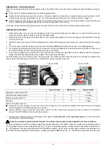
As for the setting, refer to the following chart. On this actuator, the manual control of the air damper is not provided; the setting of the
cams is carried out working by a screwdriver on the
VS
screw placed internally to the cam.
Note: to move the cams, use
Berger STA: on this actuator, the manual control of the air damper is not provided; the setting of the cams is carried out working
with a screwdriver on the
VS
screw placed on the cam.
Siemens SQN72: a key is provided to move cams I and IV, the other cams can be moved by means of screws. On the Siemens
actuator the AUTO/MAN mode is provided (see picture).
7
acting on the pressure governor of the valves group, adjust the
gas flow rate in the high flame stage
as to meet the values
requested from the boiler/utilisation:
Pressure controller is provisionally factory-set. The setting values must be locally adjusted to machine conditions.
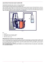
The burner is factory set with the combustion head at the position that refers to the "MAX" output. The maximum output setting refers to
the “fully-ahead” position of the combustion head (Fig. 13). As for “fully-ahead” position, it means that the head is placed inside the boi-
ler, “fully-backward” position means that the head is towards the operator. As far as the reduced output operation, progressively move
the combusiton head towards the “MIN” position, rotating clockwise the
VRT
screw (Fig. 12). The
ID
index shows how much the com-
Berger STA
Siemens SQN30
Siemens SQN72
Siemens SQN30
BERGER STA
Siemens SQN72
High flame position (set to 90°)
I
I
I (red)
Low flame and ignition position
|||
IV
III (orange)
Stand-by position (set to 0°)
II
II
II (blue)
Not used
V
III
IV (black)
I
II
III
IV
VS
I
II
III
IV
IV
III
II
I


