background image

19

At least once a year carry out the maintenance operations listed below. In the case of seasonal servicing, it is recommended to carry
out the maintenance at the end of each heating season; in the case of continuous operation the maintenance is carried out every 6
months.


ROUTINE MAINTENANCE

Check and clean the fuel filter cartdrige, replace if necessary.

Check and clean the filter inside the light oil pump: filter must be thoroughly cleaned at least once in a season to ensure correct

working of the fuel unit. To remove the filter, unscrew the four screws on the cover. When reassemble, make sure that the filter is

mounted with the feet toward the pump body. If the gasket between cover and pump housing should be damaged, it must be repla-

ced. An external filter should always be installed in the suction line upstream of the fuel unit.

Check the fuel hoses for possible leaks.

Remove, check and clean the combustion head (see page 19);

Check ignition electrodes, clean, adjust and, if necessary, replace them (see page 20);

Check and carefully clean the flame detector, replace it if necessary; if in doubt, check the detection current, once the burner starts
up (see page 21).

Remove and clean the fuel nozzle 

(Important: 

cleaning must be performed using solvent, not metal tools!

).

 At the end of

maintenance operations after the burner reassembly, light the flame and check its shape, replacing the nozzle whenever a questio-
nable flame shape appears. Whenever the burner is used intensely, we recommend preventively replacing the nozzle at the start of
each heating season.

Clean and grease sliding and rotating parts.

Removing the combustion head

1

Remove the burner cover by unscrewing the fixing screws

2

Remove the 

FR

 detection probe from its slot; disconnect the electrodes cables and remove the light oil pipe.

3

Unscrew the four screws that fasten the head ass.y

Unscrew the screws that fasten the gas manifold (

C

).

4

The operator must pull the burner towards him/her self to take the combustion head out.

5

Clean the combustion head by means of a vacuum cleaner; scrape the scale off using a metallic brush.

Note:

 to reassemble the burner, follow the procedure above in the reversed oredr.

Adjusting the electrodes and nozzle position

Fix a stable surface to lean on the burner during maintenance.

To gain access to the combustion head and to the nozzles, slacken the screw on the blast tube and remove it from the part that
remains fixed to the boiler.

To guarantee a good ignition, observe the measures shown in the table below.

Be sure to tight the screw that fix the electrodes group, before reassembling the burner.

WARNING: ALL OPERATIONS ON THE BURNER MUST BE CARRIED OUT WITH THE MAINS DISCONNECTED AND
THE FUEL MANAUL CUTOFF VALVES CLOSED!

ATTENTION: READ CAREFULLY THE “WARNINGS” CHAPTER AT THE BEGINNIG OF THIS MANUAL..

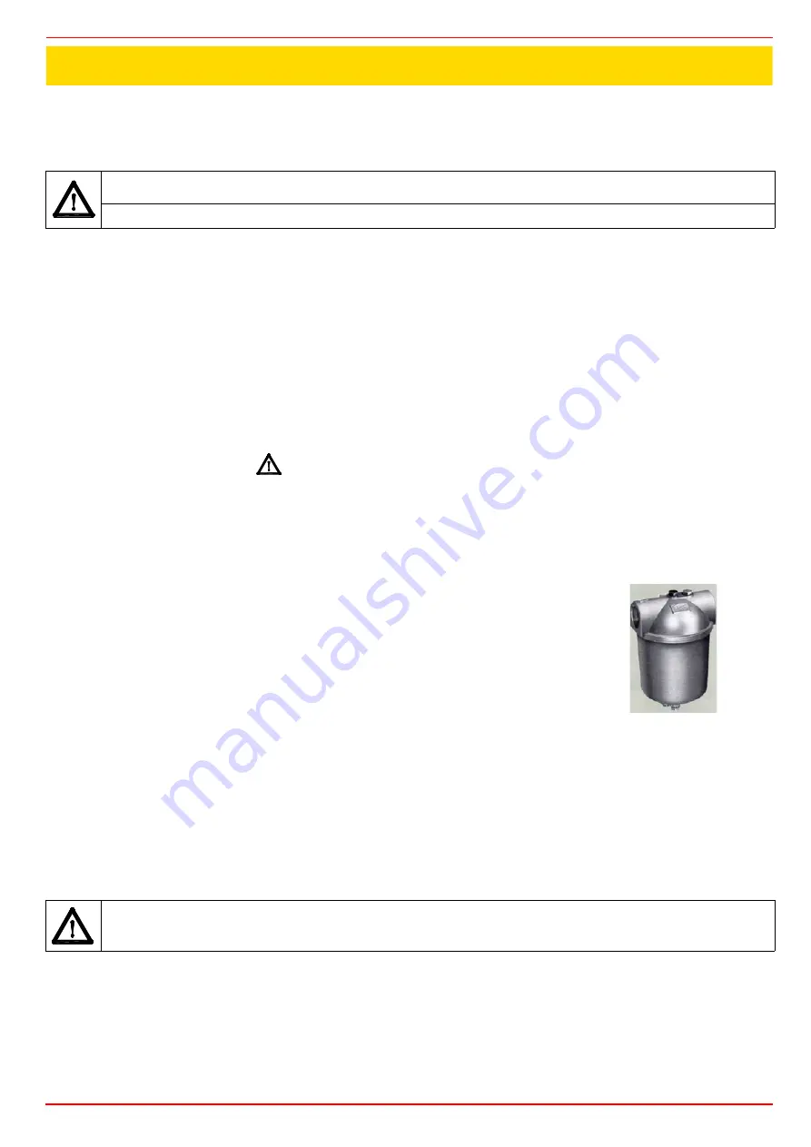
Light oil filter maintenance

For correct and proper servicing, proceed as follows:
1

cutoff the required pipe section;

2

unscrew the filter cup;

3

remove the filtering cartridge, wash it with gasoline; if necessary, replace it; check the tightening
O-rings and replace them if necessary;

4

replace the cup and restore the pipe line.

5

ATTENTION: 

avoid


the electrodes to get in touch with metallic parts (blast tube, head, etc.), otherwise the boiler operation

would be compromised. Check the electrodes position after any intervention on the combustion head. 

PART III: MAINTENANCE

Summary of Contents for G6

Page 1: ...MANUAL OF INSTALLATION USE MAINTENANCE G6 G10 G18 24 Vdc voltage supplied single stage burners M039223CC Rel 2 2 09 2012 BURNERS BRUCIATORI BRULERS BRENNER QUEMADORES...

Page 2: ......

Page 3: ...electricity gas oil or other fuel Observe caution with hot burner components These are usually near to the flame and the fuel pre heating system they become hot during the unit operation and will rem...

Page 4: ...or explosive mixtures DIRECTIVES AND STANDARDS Gas burners European directives Directive 2009 142 EC Gas Appliances Directive 2006 95 EC on low voltage Directive 2004 108 EC on electromagnetic compat...

Page 5: ...ept for some models for which a separate regulating valve is provided Other pumps are provided with two pressure regulators one for the high and one for low pressure in double stage systems with one n...

Page 6: ...e boiler manufacturer In absence of these consider the fol lowing Cast iron boilers three pass flue boilers with the first pass in the rear part the blast tube must protrude no more than 100 mm into t...

Page 7: ...1 BURNER TYPE G6 G10 G18 2 FUEL G Light oil 3 OPERATION TN Single stage 4 BLAST TUBEBLAST TUBE S Standard L Extended 5 DESTINATION COUNTRY see data plate 6 BURNER VERSION Y Special version 24Vdc power...

Page 8: ...rea ched setting the combustion head to its MIN position During the first ignition the combustion head is set in order to find a compromise between the burner output and the generator specifications...

Page 9: ...door of the combustion chamber as described on paragraph Overall dimensions 2 place the burner to the boiler lift it up and handle it according to the procedure described on paragraph Handling the bu...

Page 10: ...re gravity or ring feed systems are provided install an automatic interception device see n 4 Fig 7 Fig 4 Gravity circuit Fig 5 Ring circuit Fig 6 Suction circuit Key 1 Manual valve 2 Light oil filter...

Page 11: ...he case of gravity feed as decribed before To change from a 1 pipe system to a 2 pipe system insert the by pass plug G as for ccw rotation referring to the pump shaft Caution Changing the direction of...

Page 12: ...en for a considerable length of time for example when there is a long suction line to bleed To avoid damages inject some lubrication oil into the vacuum inlet Care must be taken when installing the pu...

Page 13: ...e rotating nut of the two flexible hoses on the pump being careful to avoid exchanging the inlet and return lines see the arrows marked on the pump that show the inlet and the return see prevoius para...

Page 14: ...the cover Respect the basic safety rules make sure of the connection to the earthing system do not reverse the phase and neutral connections fit a differential thermal magnet switch adequate for conne...

Page 15: ...tion air excess must be adjusted according to the in the following chart Recommended combustion parameters Fuel Recommended CO2 Recommended O2 Light oil 11 5 13 2 9 4 9 Keys EV1 Light oil solenoid val...

Page 16: ...ig 10 and light it up 5 bleed the air from the M pressure gauge port of the pump P slightly loosing the cao and without removing it Fig 10 Caution The nozzle flow rate at 12bar must be higher than the...

Page 17: ...ting the combsution head Turn VRTclockwise or counterclockwise according to the output to gain minimum or maximum If the combustion head is to be replaced the position on Fig 16 Tab 2 must be observed...

Page 18: ...ERATION ALSO FUNCTIONS AS AN EMERGENCY SWITCH AND ON THE RESET BUTTON IN CASE OF A BURNER SHUT DOWN RESET THE CONTROL BOX BY MEANS OF THE RESET PUSHBUTTON IF A SECOND SHUT DOWN TAKES PLACE CALL THE TE...

Page 19: ...rotating parts Removing the combustion head 1 Remove the burner cover by unscrewing the fixing screws 2 Remove the FR detection probe from its slot disconnect the electrodes cables and remove the lig...

Page 20: ...dry and clean cloth 5 if necessary replace the photoresistor 6 replace the photoresistor into its slot 7 Checking the detection current Before turning the burner on or in case of maintenance check the...

Page 21: ...m SE01 555 BURNER DOES NOT START UP REPETITION OF PRE PURGING NOISY LIGHT OIL PUMP BUNRER DOES NOT START UP AND LOCKS OUT BUNRER STARTS UP AND LOCKS OUT BUNRER LOCKS OUT DURING OPERATION BUNRER LOCKS...

Page 22: ...MPER 12 3 PLATE 12 4 BASE 12 5 BASE 12 6 GASKET 12 7 COUPLING 12 8 BRACKET 12 9 BRACKET 12 10 HEAD ADJUSTING SCREW 12 11 INDEX LABEL 12 12 INDEX 12 13 FAIRLEAD 12 14 NUT 12 15 BURNER HOUSING 12 16 MOT...

Page 23: ...23...

Page 24: ...tion transformer and goes to run ning position At the end of safety time in the double stage controllers the ignition transformer is de energized and contemporaneously the output of the second oil val...

Page 25: ...mption 220V 50Hz 6 5 VA 12V 24V 1VA Internal fuse For 220V and 110V supply voltage 6 3 A time delay For 24V and 12V supply voltage 10 A time delay Externsl fuse For 220V and 110V supply voltage 4 A fa...

Page 26: ......

Page 27: ......

Page 28: ...nd data subject to change Errors and omissions excepted C I B UNIGAS S p A Via L Galvani 9 35011 Campodarsego PD ITALY Tel 39 049 9200944 Fax 39 049 9200945 9201269 web site www cibunigas it e mail ci...

Reviews: