Sheet 1
Page 4
5.
S/RF (Signal/RF) Meter
Shows the strength of the received signal or the RF output.
6.
Channel Indicator
Displays the channel currently in use.
7.
Microphone Jack
Connects to the included detachable electret microphone.
8.
Volume Control
Powers on the radio and adjusts the volume.
9
Squelch knob
Adjusts the level at which the radio squelches or suppresses weak
radio signals.
10.
RF Gain Knob
Adjusts the level of the signal reception.
11.
Channel Selector
Selects which channel the radio will transmit or receive on.
Back
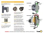
12.
Model label
Shows the model
number, FCC ID
number and serial
number.
13
. Antenna
Connector
Connects to a
male PL-259
external antenna
cable (antenna
sold separately).
14.
PA Speaker Jack
See
Connecting external speakers
, below.
15.
External Speaker Jack
See
Connecting external speakers
, below.
16.
12 Volt DC Power Cord
17.
Fuse casing
Microphone
18
Push-to-talk (PTT) button
NOTE: Make sure you have read and understood part 95 of the FCC
rules and regulations before using the transmitter.
MODEL: PRO520XL
FCC ID
SERIAL NO:
13
16
17
15
12
14
18


