background image

ENDAT-AJ01 USERS MANUAL 

UNICORN COMPUTER CORP. 


21 

J1: DC Input connector (1x2 with 3.96mm) 

Pin No. 

Signal 

GND 

+12V 


J1: DC Input connector (2x2 with ATX_12V) 

Pin No. 

Signal 

-V 

-V 

+V 

+V 


Notice:  The Input "+12V" voltage.  


HDDPWR1: DC Output connector (1x4 with 3.96mm) 

Pin No. 

Signal 

+12V 

GND 

GND 

+5V 


CN12: Mini DP Connector 


Summary of Contents for ENDAT-AJ01

Page 1: ...ENDAT AJ01 USERS MANUAL UNICORN COMPUTER CORP 1 ENDAT AJ01 User s Manual For A2 or later version of ENDAT AJ01 Document version 1 2 Release Date Nov 27 2014...

Page 2: ...usiness Machines Corporation Intel is a registered trademark of Intel Corporation VIA is registered trademark of VIA Technology Incorporation Plug and Play is registered trademarks of Intel Corporatio...

Page 3: ...el Up to DDR3 1333MHz The maximal capacity is up to 8GB Ethernet Dual Realtek 8111E Gigabit LAN Display Support CRT LVDS DP LVDS support 24 bit dual channel via CH7511B through eDP Support 18 24 36 48...

Page 4: ...nnector 2 x RJ 45 connector Mini DP Port connector 1 x SPK out Jack I O Onboard ENDAT AJ01 ENDAT AJ01S PS2 Keyboard Mouse with 2 54mm Pin Header COM2 COM3 COM4 2 54mm Box Header COM1 COM2 COM3 COM4 2...

Page 5: ...GE PRECAUTIONS 9 1 4 MOTHERBOARD LAYOUT 10 CHAPTER 2 SETTING UP THE MOTHERBOARD 12 2 1 JUMPERS AND CONNECTORS 12 2 2 INSTALLING MEMORY 24 2 3 SHARED VGA MEMORY 24 2 4 WATCH DOG TIMER 24 2 5 DIGITAL I...

Page 6: ...400E clocked at 600MHz GX 217GA AMD Radeon HD 8280E clocked at 450MHz GX 210HA AMD Radeon HD 8210E clocked at 300MHz GX 210JA AMD Radeon HD 8180E clocked at 300MHz which supports Microsoft DirectX 11...

Page 7: ...ture and UMA mode shares system memory Auto or up to 4G a GX 420CA AMD Radeon HD 8400E clocked at 600MHz b GX 217GA AMD Radeon HD 8280E clocked at 450MHz c GX 210HA AMD Radeon HD 8210E clocked at 300M...

Page 8: ...ore ENDAT AJ01 17 embeds GX 217GA SoC with AMD Radeon HD 8280E 1 65GHz dual core ENDAT AJ01 10 embeds GX 210HA SoC with AMD Radeon HD 8210E 1 0GHz dual core ENDAT AJ01S 20 slim line design omit upper...

Page 9: ...tems is missing or damage please contact the dealer whom you purchase the motherboard from Save the shipping material and carton in the event that you want to ship or store the board in the future Not...

Page 10: ...ENDAT AJ01 USERS MANUAL UNICORN COMPUTER CORP 10 1 4 AJ01 MOTHERBOARD LAYOUT...

Page 11: ...ENDAT AJ01 USERS MANUAL UNICORN COMPUTER CORP 11 AJ01S MOTHERBOARD LAYOUT...

Page 12: ...S1 LCD Backlight Control Connector CN3 USB2 0 Connector CN9 10 N A USB2 0 Header J4 USB 3 0 Connector J9 LAN1 Connector CN9 CN6 LAN2 Connector CN10 CN7 COM1 Connector Box Header COMVGA1 CN5 COM2 Box H...

Page 13: ...LCD Backlight Voltage Select JP8 LVDS1 LCD Backlight Control Voltage Select JP5 Clear CMOS JBAT1 PS 2 Mouse KB Voltage Selector JP6 COM1 2 Voltage Selector JP7 COM3 4 Voltage Selector JP3 RS232 485 Se...

Page 14: ...with 2 0mm Pin 2 3 Normal Pin 1 2 Close for clear CMOS JP6 PS 2 Mouse KB Voltage Selector 1x3 with 2 0mm Voltage 5VSUS 5V JP1 1 2 2 3 JP7 JP3 COM Port Voltage Selector 2x6 with 2 0mm Voltage 12V DC R...

Page 15: ...0mm LVDS1_Pin 7 8 33 34 3 3V 5V 12V JP4 1 2 3 4 5 6 J8 LCD Backlight Voltage Select 1x3 with 2 0mm LVDS1_Pin1 2 39 40 5V 12V JP8 1 2 2 3 JP5 LCD Backlight Control Voltage Select 1x3 with 2 0mm LVDS_P...

Page 16: ...rs J1 PS 2 Keyboard Mouse Header 2x5 with 2 54mm Pin No Signal KB Pin No Signal MS 1 KB Data 2 MS Data 3 KEY 4 KEY 5 GND 6 GND 7 5V DC 8 5V DC 9 KB_CLK 10 MS_CLK JKBMS1 External PS 2 Device Header 2x7...

Page 17: ...7 GND 15 DDC CLK 8 GND D SUB Type Connector for COM1 port RS 232 Pin No Function Pin No Function 1 DCD 6 DSR 2 RXD 7 RTS 3 TXD 8 CTS 4 DTR 9 RI 5 GND CN4 COM2 CN2 COM3 CN1 COM4 Box Headers 2x5 with 2...

Page 18: ...LPT1 Printer Port Box Header 2x13 with 2 0mm Pin No Description Pin No Description 1 STB 10 ACK 2 PD0 11 BUSY 3 PD1 12 PE 4 PD2 13 SLCT 5 PD3 14 AFD 6 PD4 15 ERR 7 PD5 16 INIT 8 PD6 17 SLIN 9 PD7 18 2...

Page 19: ...JACK DETECT 4 GND 5 AUDIO GND 6 GND 7 LINE Out R 8 CD_IN_R J7 LINE IN MIC Header 2 x 4 with 2 0mm Pin No Signal Pin No Signal 1 LINE IN L 2 MICIN1_L 3 JACK DETECT 4 JACK DETECT 5 AUDIO GND 6 AUDIO GN...

Page 20: ...I O Header 2x7 with 2 0mm Pin No Signal Pin No Signal 1 5V 2 5V 3 DIO OUT0 4 DIO IN0 5 DIO OUT1 6 DIO IN1 7 DIO GND 8 DIO GND 9 DIO OUT2 10 DIO IN2 11 DIO OUT3 12 DIO IN3 13 3 3V 14 3 3V FAN1 FAN2 Co...

Page 21: ...put connector 1x2 with 3 96mm Pin No Signal 1 GND 2 12V J1 DC Input connector 2x2 with ATX_12V Pin No Signal 1 V 2 V 3 V 4 V Notice The Input 12V voltage HDDPWR1 DC Output connector 1x4 with 3 96mm Pi...

Page 22: ...ive low pulse 0V from this pin3 PWRDN Example Using button switch on Pin1_GND Pin3_ PWRDN LVDS_BKLT_CTRL for backlight brightness dimming PWM duty cycle range from 30 100 the output frequency from PWM...

Page 23: ...2 17 Odd 3 18 Odd 3 19 Odd CLK 20 Odd CLK 21 GND 22 GND 23 Even 0 24 Even 0 25 Even 1 26 Even 1 27 Even 2 28 Even 2 29 Even 3 30 Even 3 31 Even CLK 32 Even CLK 33 LCD POWER 34 LCD POWER 35 GND 36 GND...

Page 24: ...D Radeon HD graphic engine whit UMA Auto or up to 4GB of System Memory The amount of video memory on motherboard determines the number of colors and the video graphic resolution 2 4 Watch Dog Timer Wa...

Page 25: ...ortb 0x2f 0x00 set register value Default 00h bit7 Mouse interrupt reset enables watch dog timer reload 0 Watchdog Timer I is not affected by mouse interrupt 1 Watchdog Timer I is reset by mouse inter...

Page 26: ...7 6 5 4 3 2 1 0 Map DIO I3 DIO I2 DIO I1 DIO I0 NA NA NA NA Sample code for input using Turbo C C 3 0 define input_port 0x2f Digital input data port Unsigned char read_data outportb 0x2e 0x87 Unlock r...

Page 27: ...ck register outportb 0x2e 0x07 set Logic Device number pointer outportb 0x2f 0x07 set Logic Device number outportb 0x2e 0x30 set Device Active outportb 0x2f 0x02 set Bit 2 GPIO2 0 Inactive 1 Active De...

Page 28: ...ing Use the BIOS CMOS setup program to modify the system parameters to reflect the environment installed in your system and to customize the system as desired Press the F2 key to enter into the BIOS C...

Page 29: ...te and time Use the TAB and BACKTAB SHIFT TAB keys System Information This submenu provides information about the system BIOS Version CPU and memory as shown in Figure The following table describes th...

Page 30: ...gs associated with the FCH Options SATA Configuration SATA Controller En Disable SATA Port SATA Mode Select the SATA controllers operation mode IDE AHCI SATA PORT 1 SATA Port1 Disk Information SATA PO...

Page 31: ...with the SIO Configuration Serial Port Setting Serial Port 1 4 COM2 Type Select Serial 2 type RS232 RS485 RS422 UART2 Termination For RS485 RS422 Termination Parallel Port Setting Parallel Port Watch...

Page 32: ...Flash file 5 Once the BIOS is Flash successfully Reboot the system 6 Press F2 to enter BIOS Setup Load BIOS setup default F9 save BIOS default and exit F10 Please turn off system and clear CMOS data b...

Page 33: ...5 Odd 2 16 Odd 2 17 Odd 3 18 Odd 3 19 Odd CLK 20 Odd CLK 21 GND 22 GND 23 Even 0 24 Even 0 25 Even 1 26 Even 1 27 Even 2 28 Even 2 29 Even 3 30 Even 3 31 Even CLK 32 Even CLK 33 LCD POWER 34 LCD POWER...

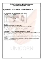
Page 34: ...eceiving active low pulse 0V from this pin3 PWRDN Example Using button switch on Pin1_GND Pin3_ PWRDN LVDS_BKLT_CTRL for backlight brightness dimming PWM duty cycle range from 30 100 the output freque...

Page 35: ...mproper using or use of unauthorized parts The following situations will be charged 1 The products during the warranty but defective caused by improper using or artificial external pressure and result...

Page 36: ...pped with your returns Service cannot begin until we have this information RMA NO Company Person to Contact Phone No Purchase Date Fax No Applied Date Return Shipping Address Model No Serial No Proble...

Reviews: