UM980eb User Manual
10
Antenna Circuit
UC-08-M32 EN R1.0
V_BCKP.
In the case of normal power supply to the evaluation board, the micro battery charging
circuit on the board will automatically charge the micro battery.
If the evaluation board has been placed for a long time, the power of the battery may be
low and the hot start test may fail. Therefore, it is recommended to charge the board as
long as possible before testing the hot start function.
1)
Use a multimeter to measure the voltage of the micro battery. If the voltage is above 2.6 V
and is stable, it indicates that the power of the micro battery is sufficient.
2)
Use a multimeter to measure the voltage of the micro battery. If the voltage drops rapidly, it
indicates that the power of the micro battery is insufficient.
3)
When the micro battery runs out of power, it will take more than 96 hours to fully charge the
battery.
4)
Under normal circumstances, after powering the evaluation board for one night, the hot start
test can be done normally the next day.
4
Antenna Circuit
4.1
Antenna Detection Circuit
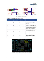
The antenna detection circuit consists of a MOS switch, a current detection chip and
two buffers.
The antenna feed supply can be selected from the 5 V DC/DC circuit output or VCC_RF
(supplied by the module). VCC_RF provides 3.3 V voltage, but the circuit has less
protective design; therefore, it is not recommended to use VCC_RF to supply power to
the antenna.
U6 and U2 are two buffers with open-drain output. ANT_OFF1 needs to be pulled up
through ANT_BIAS1 to make sure that MOS can be turned off.
The current threshold can be adjusted by changing the resistance value of
R24/R13/R14. Since the feed current flowing through R24 will generate a voltage drop,
this solution is not suitable for antennas with high power consumption.

