


LEDs
Per Device:
Power
Per Por t:
LNK (Link)
ACT (Activity)
FDX (Full Duplex)
The LED Indicators gives real-time information of systematic operation
status. The following table provides descriptions of LED status and their
meanings.
Activity Status LEDs
TX: Transmit Data
RX: Receive Data
7
LED
Status
Color
Description
Power
On
Green
The switch is supplied with
suitable power.
On
Yellow
The por t is successfully
connected to a device.
LNK/ACT
Blinks
Yellow
The por t is transmitting or
recieving data.
On
The por t is NOT successfully
connected to a device.
100
On
Yellow
The por t is operating at
100Mbps
On
Green
The por t is operating in Full-
Duplex mode.
FDX/COL
Blinks
Green
The por t is experiencing data
collisions.
Off
No device connected or if
the LINK/ACT light is on, por t
is connecting in Half-duplex
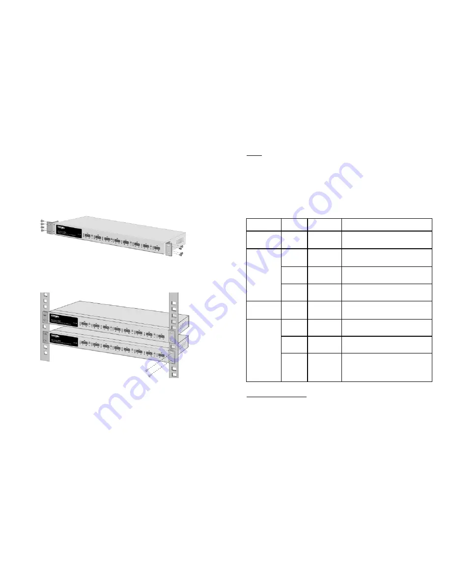
Rackmount Installation
Included with the
Pro-Switch/8F
are brackets allowing the switch to be
mounted in a standard EIA-sized, 19-inch rack. The Switch can be placed
in a wiring closet with other equipment.
Per form the following steps to rack mount the switch:
A.
Align one bracket with the holes on one side of the switch and secure
it with the small bracket screws. Then attach the remaining bracket to
the other side of the Switch.
B.
After attaching both mounting brackets, position the
Pro-Switch/8F
in
the rack by lining up the holes in the brackets with the appropriate
holes on the rack. Secure the Switch to the rack with a screwdriver
and the larger rack-mounting screws.
Note:
For proper ventilation, allow at least 4” ( 10 cm ) of clearance at the front
and 3.4” ( 8 cm ) at the back of the Switch. This is especially impor tant for
an enclosed rack installation.
10
Figure 4. Attach mounting brackets with screws
Figure 5. Attach switch to rack
Summary of Contents for Pro-Switch 8F
Page 2: ......


