background image

Page  29.

Mounting the HotPort 

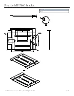
Using the Universal Mounting Bracket

Firetide’s HotPort can be mounted to a wall or onto a vertical 

or horizontal pole. The HotPort’s universal mounting bracket 

provides holes and slots for use with the provided mounting 

kit or for straps (not included) or other mounting methods. 

Before mounting, keep in mind that adequate space is needed 

around the mounting bracket to allow the HotPort unit to 

slide onto it and to enable cable connections.

Remove the Universal Mounting Bracket from the 

HotPort

 The universal mounting bracket is shipped 

attached to the HotPort node. To remove the universal 

bracket, first loosen the four thumb screws, two on each 

side, then slide the universal bracket toward the connector 

side of the HotPort node and lift off. 

Wall Mounting

Mount the universal mounting bracket to a wall using two 

holes near the top and two holes near the bottom of the 

universal bracket. Use appropriate screws (not provided) and 

anchors as required by wall construction and materials to 

safely and securely support the HotPort. Once the universal 

bracket has been mounted, attach the HotPort by reversing 

the bracket removal procedure.

Pole Mounting

POLE 37–50 MM DIAMETER

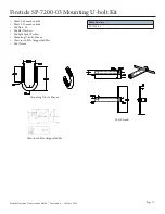
Use Firetide’s SP-7200-03 u-bolt mounting kit, provided with 

each HotPort, to mount the universal mounting bracket onto 

a 37–50 mm diameter pole.

1. Using claw-tooth gripper saddles, washers, split washers

then nuts, install the two u-bolts onto the mounting pole.

Temporarily  allow  enough  play  to  snuggly  slide  or  spin

the u-bolts on the pole.

2. Use the position of screw slots in the universal mounting

bracket as a guide to correctly position the two u-bolts on

the pole. For mounting stability, target screw slots that will

allow the u-bolts to be positioned far from each other.

3. Once properly positioned, securely tighten the two u-bolts

to the pole.

4. There should be about 12–15 mm (1/2–5/8”) of u-bolt

threaded end sticking out beyond each nut. This is the

bolt length needed to mount the universal bracket. If the

lengths are longer, then on each u-bolt end, install a

second nut until there is 12-15 mm of thread between the

second nut and u-bolt end (see photos at right).

5. Slip a flat washer onto each of four u-bolt ends.

6. Attach the universal bracket by positioning the u-bolt

ends into the bracket’s screw slots. Use washers, then lock

washers and nuts to secure the universal bracket to the u-

bolts.

7. Recheck all nuts for adequate tightness. Confirm that the

universal bracket does not slip or turn on the pole.

8. Attach the HotPort to the universal mounting bracket by

reversing the bracket removal procedure.

POLE GREATER THAN 50 MM DIAMETER

Use appropriate mounting straps (not included) or other

secure means to mount a HotPort universal mounting

bracket onto a 50 mm (2.0”) or larger diameter pole,

irregularly shaped pole, or light pole.

1. Position the universal mounting bracket against the pole.

2. Wrap a mounting strap around the pole and through

the vertical slots located near the top of the universal

mounting bracket.

3. Do the same with a second strap but this time use the

vertical slots near the bottom of the universal bracket.

4. Secure the mounting straps so that the bracket will not

slip or turn on the pole.

5. Attach the HotPort to the universal mounting bracket by

reversing the bracket removal procedure.

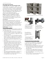
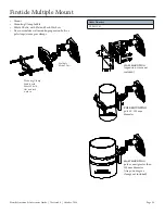
Universal mounting bracket attached to pole using u-bolts

U-bolt* mounted on pole—note 

addition of secondary nuts 

(circled) to meet 12–15 mm 

bolt length required by the 

universal mounting bracket. 

The HotPort universal 

mounting bracket can be 

mounted on vertical and 

horizontal poles using u-bolts* 

or other proper fastening 

hardware. 

continued from previous page

Universal mounting 

bracket mounted onto a 

pole using two u-bolts* 

with additional secondary 

nuts.

* photos for quick reference only 

—all u-bolts should be

secured using proper washers

& lock washers in addition to

nuts.

12–15 mm 

Firetide Antenna & Accessories Guide  |  Version 4.0  |  October 2014 

Summary of Contents for Firetide AO-024-MIMO-8

Page 1: ...site www firetide com for current information 2014 Firetide Inc A Divion of UNICOM Global HotPort HotPoint HotClient HotView HotView Pro MeshBridge and AutoMesh are registered trademarks of Firetide I...

Page 2: ...some high gain antennas may exceed EIRP limits in some countries Indoor antennas have RP SMA connectors compatible with Firetide HotPort indoor mesh nodes and HotPoint indoor access points The outdoor...

Page 3: ...10 meter North America AC power cable PO 010 E 7000 series outdoor rated 10 meter EU and Korea AC power cable PO 010 C 7000 series outdoor rated 10 meter UK Singapore AC power cable 7020 1001 6 pin F...

Page 4: ...p a layer of electrical tape STICKY SIDE OUT over the connector from base of unit to one inch over the cable When wrap ping the tape should overlap about 40 of the previous turn on each turn This laye...

Page 5: ...uppressor connection Step 6 Using plenty of tension tightly wrap a layer of butyl rubber splicing mastic tape over the electrical tape Overlapping the tape about 40 on each turn start from base of uni...

Page 6: ...ed for indoor use only and recommend ed application is to use in network staging process continued on next page Electrical Specifications Value Frequency Range 2 4 5 X GHz Gain 3 dBi Radiation Pattern...

Page 7: ...Page 7 Firetide 2 4 and 5 X GHz Dipole Staging Antenna continued from previous page Firetide Antenna Accessories Guide Version 4 0 October 2014...

Page 8: ...ring seal in the base of the antenna with integrated connector at the base Assures a watertight seal to prevent water from migrating into the antenna connector Features High gain low VSWR Small size...

Page 9: ...retide A0 024 MIMO 8 Omnidirectional Antenna Antenna L type bracket Mast supplied by customer 600mm 145 mm 145 mm 600 mm continued from previous page Firetide Antenna Accessories Guide Version 4 0 Oct...

Page 10: ...LAN system Support IEEE802 11a b g n Indoor hotspot coverage Features Suitable for indoor use Ceiling mount Space diversity MIMO technique continued on next page Firetide AOI 245 MIMO 25 Antenna Order...

Page 11: ...Page 10b continued from previous page Firetide AOI 245 MIMO 25 Antenna Firetide Antenna Accessories Guide Version 4 0 October 2014...

Page 12: ...5 GHz Gain 7 4 dBi Nominal Impedance 50 ohms VSWR 1 5 Max Radiation Pattern Omnidirectional Vertical Beam Width 20 Polarization Vertical Connector N female Operating Temp Range 20 C to 65 C Wind Survi...

Page 13: ...time and improves overall effectiveness Internal o ring seal in the base of the antenna with integrated connector at the base Assures a watertight seal to prevent water from migrating into the antenna...

Page 14: ...retide A0 050 MIMO 9 Omnidirectional Antenna Antenna L type bracket Mast supplied by customer 600mm 145 mm 145 mm 600 mm continued from previous page Firetide Antenna Accessories Guide Version 4 0 Oct...

Page 15: ...base of the antenna with integrated connector at the base Assures a watertight seal to prevent water from migrating into the antenna connector Applications 5 1 5 5 5 8 GHz WLAN System 5 8GHz UNII ISM...

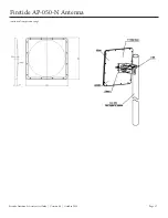
Page 16: ...5 Firetide AO 050 N Antenna continued from previous page Antenna Connector Mast 60 mm diameter supplied by customer Splint Hose Clamp 20 mm 570 mm Firetide Antenna Accessories Guide Version 4 0 Octobe...

Page 17: ...s 5 8 GHz ISM applications IEEE802 11a g WiFi Wireless Bridges Client Antenna Features 5 1 5 5 5 8 GHz Tri band High gain Low profile Light weight All weather operation DC Ground for lightning protect...

Page 18: ...Page 17 continued from previous page Firetide AP 050 N Antenna Firetide Antenna Accessories Guide Version 4 0 October 2014...

Page 19: ...1 GHz Triple polarization MIMO application High gain Low VSWR Strong corrosion resistance ability continued on next page Electrical Specifications Value Frequency Range 4900 6100 MHz Bandwidth 975 MHz...

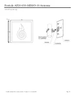
Page 20: ...Page 19 Firetide AP20 050 MIMO 19 Antenna continued from previous page Firetide Antenna Accessories Guide Version 4 0 October 2014...

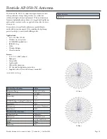
Page 21: ...stem 5 GHz UNII ISM system Point to point or point to multipoint Broad band 4 9 5 1 5 5 5 8 GHz MIMO application High gain Low VSWR Strong corrosion resistance ability Electrical Specifications Value...

Page 22: ...ient Antenna Wireless Bridge Features High Precise Parabolic Dish UV Coated Aluminum Alloy V H Dual Polarization Standard Mounting Kits continued on next page Electrical Specifications Value Frequency...

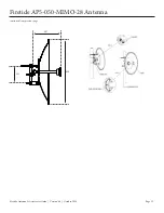
Page 23: ...Page 22 Firetide AP5 050 MIMO 28 Antenna continued from previous page 950 407 252 Firetide Antenna Accessories Guide Version 4 0 October 2014...

Page 24: ...ng protection helps to meet local electrical building codes Typical Value Frequency Range 4 9 6 1 GHz Gain 16 dBi Nominal Impedance 50 ohms VSWR 1 8 Max Radiation Pattern Directional Vertical Beamwidt...

Page 25: ...eatures 4 9 5 5 5 8 6 1 GHz Triple polarization MIMO application Medium gain Low VSWR Strong corrosion resistance ability continued on next page Order Number AS90 050 MIMO 16T Electrical Specification...

Page 26: ...Page 25 Firetide AS90 050 MIMO 16T Antenna continued from previous page Firetide Antenna Accessories Guide Version 4 0 October 2014...

Page 27: ...Page 26 Firetide MT 7100 Bracket Order Number MT 7100 Firetide Antenna Accessories Guide Version 4 0 October 2014...

Page 28: ...20mm hex bolts M6 Nuts SS M6 Flat Washers M6 Split Lock Washers Mounting U bolts 80mm Claw tooth Pole Gripper Saddles M6 Wrench Order Number SP 7200 03 Mounting U bolt 80 mm M6 Wrench Claw tooth Pole...

Page 29: ...se non vulcanized rubber weatherproofing kits to weatherproof connectors and antennas Preparing Earth Ground The HotPort node must be properly connected to earth ground Failure to do so may result in...

Page 30: ...d be about 12 15 mm 1 2 5 8 of u bolt threaded end sticking out beyond each nut This is the bolt length needed to mount the universal bracket If the lengths are longer then on each u bolt end install...

Page 31: ...ps worm gear clamps Order Number SP MNT 01 WALL MOUNTING expansion screws not included POLE MOUNTING pole 50 120 mm diameter MAST MOUNTING pole or mast greater than 120 mm diameter straps worm gear cl...

Page 32: ...radiation field and is most important t BJO PCF FBN 5IF EJSFDUJPO PG NBYJNVN JOUFOTJUZ t 4JEF PCFT FBN 5IF SBEJBUJPO MPCFT JO BOZ EJSFDUJPO PUIFS than that of the main lobe t FBNXJEUI 5IF BOHMF XIFSF...

Page 33: ...or maintained in a manner not described in the product user manual or if the product has been altered in any way or if product serialization has been altered Any attempt to disassemble or repair the...

Reviews: