background image


7


Rack-mounted Installation


The  DYNA-SWITCH/24  comes  with  a  rack-mounting  kit  (not  a  standard 

option  for  this  switch) and  can  be  mounted  in  any  EIA  standard  sized,  19" 

rack. The Switch can then be placed in a wiring closet with other equipment.  


Perform the following steps to rack mount the switch: 

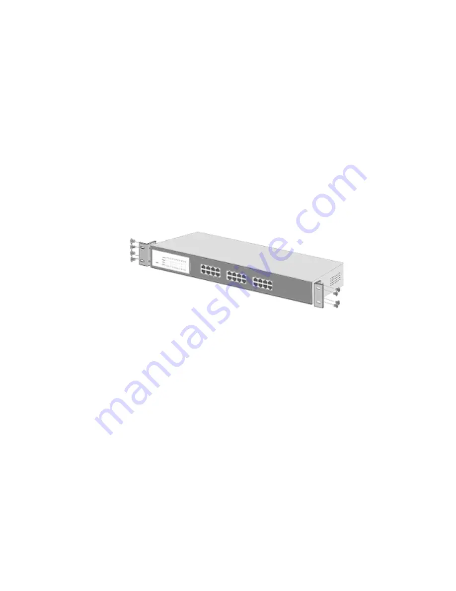
1.  Position one bracket to align with the holes on one side of the switch and 

secure  it  with  the  smaller  bracket  screws.  Then  attach  the  remaining 

bracket to the other side of the Switch. 


Attach mounting brackets with screws 


2.  After attached both mounting brackets, position the DYNA-SWITCH/24 in 

the rack by lining up the holes in the brackets with the appropriate holes 

on  the  rack.  Secure  the  switch  to  the  rack  with  a  screwdriver  and  the 

rack-mounting screws. 


Power On  

Connect the power cord to the power socket on the rear panel of the Switch. 

The  other  side  of  power  cord  connects  to  the  power  outlet.  The  external 

power  supplies  AC  in  the  100-240VAC  voltage  range,  frequency  50~60Hz. 

Check  the  power  indicator  on  the  front  panel  to  ensure  power  is  properly 

supplied. 

Summary of Contents for fep-31024t-2

Page 1: ...24 Port 10 100Base TX Fast Ethernet Switch Dyna Switch 24 USER S MANUAL FEP 31024T 2 rev 2...

Page 2: ...earn and store source address on a 4K entry MAC address table It also supports Class of Service functions No manual configuration is necessary The CoS function is included in the switch firmware and w...

Page 3: ...2 0 Switch Power Cord Four Rubber Feet User manual Rack Mount kits DYNA SWITCH 24 Rev 2 0 User manual Rubber Feet Power Cord Rack Mount Kits Package Contents Compare the contents of your DYNA SWITCH...

Page 4: ...hing eliminated unnecessary transmissions that slow a network This is accomplished by employing address learning which replaced the inefficient receiving port Auto negotiation regulates the speed and...

Page 5: ...of the Switch Front panel of the DYNA SWITCH 24 Rev 2 0 RJ 45 ports Auto MDI MDIX 24 10 100Mbps auto sensing ports for 10Base T or 100Base TX device connections MDI Medium Dependent Interface ports ar...

Page 6: ...ns of LED Indicators LED Status Description Green Power On Powe r Off Power is not connected Green The port is connecting with the device Blinks The port is receiving or transmitting data LK A CT Off...

Page 7: ...th a power outlet nearby The surface should be clean smooth level and sturdy Make sure there is enough clearance around the Switch to allow air circulation and the attachment of cables and the power c...

Page 8: ...remaining bracket to the other side of the Switch Attach mounting brackets with screws 2 After attached both mounting brackets position the DYNA SWITCH 24 in the rack by lining up the holes in the bra...

Page 9: ...interconnecting networking segments PC workstations and servers can communicate with each other by directly connecting with the DYNA SWITCH 24 The switch automatically learns nodes address which are s...

Page 10: ...Small Workgroup The DYNA SWITCH 24 can be used as a standalone switch to which personal computers servers or a printer server are directly connected to form a small workgroup Small Workgroup Applicati...

Page 11: ...o the corporate backbone In the illustration below two Ethernet switches with PCs a print server and a local server attached are connected to the DYNA SWITCH 24 Each device in this network can communi...

Page 12: ...4K Mac address table LED Indicators Per port Link Activity Full duplex Collision Per unit Power Network Cable 10Base T 2 pair UTP STP Cat 3 4 5 cable EIA TIA 568 100 ohm 100m 100Base TX 2 pair UTP STP...

Page 13: ...4 high queue packets then 1 low queue packet Note The CoS function is included in the switch firmware and will operate automatically when the switch is on Storage Temp 10 C to 70 C 40 F to 158 F Opera...

Page 14: ...AL...

Reviews: