33
Instructions for the installer
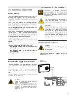
The BCM
(optional kit)
board, elaborates the data con-
cerning the thermal drop (
Δ
t between primary flow and
return) and provided power.
When the provided power is reduced, the number of turns
of the pump reduces as well and therefore also the hourly
flow rate, keeping the thermal drop constant.
.
Boiler battery
IThe 0 - 10 Volt modulation signal is reset at:
- 3 Volt for minimum speed
- 10 Volt for maximum speed.
These values can be modified according to the
pump model used. For further information of
the 0 - 10 Volt signal, also refer to the pump
manual.
FIX RATE PUMP
Modulating Pump
1
2
3
Y2
4
5
6
7
Y3
1
2
3
Jp1
1
2
3
Y4
4
DL1 DL2
DL3
1
2
3
Y1
4
5
6
A1
SW1
AL
L
A
R
M
SI
G
N
A
L
BCM
eB
U
S
-
eB
U
S
+
+ 2
4
V
MAIN SUPPLY
230 V - 50 Hz
N
L1
N
0-10 V terminals
Wilo modulating
pump interface
(-
)
(0
- 1
0
V
)
L1
SUPPLY
MODULATION
PUMP
APM
MODULATING PUMP
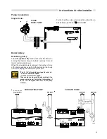
Pump Connection
FIXED
RATE PUMP
Single Boiler
12
L
1
N
MARRONE
MARRONE
BLU
BLU
GIA/VER
GIA/VER
M1
P
- For the fixed flow rate pump connection, place the ca-
bles between pin
1.2
and
terminal
M1
.
1
2
3
Y2
4
5
6
7
Y3
1
2
3
Jp1
1
2
3
Y4
4
DL1 DL2
DL3
1
2
3
Y1
4
5
6
A1
SW1
ALLARM
SIGNAL
PUMP
BCM
eB
U
S
-
eB
U
S
+
+ 2
4
V
MAIN SUPPLY
230 V - 50 Hz
N
L1
N
L1
MAIN SUPPLY
230 V - 50 Hz
P
RELE’
N
L


