background image

Unibrain Fire-i 530/550/630/830/850 Operation Manual 

Page 56 


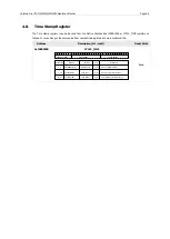
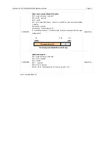
Note that 1394 data consist of 32 bit data the data read should 

Bit 0 ~ Bit 7    : 1

st

 Data    


Bit 8 ~ Bit 15    : 2

nd

 Data 

Bit 16 ~ Bit 23    : 3

rd

 Data 


Bit 24 ~ Bit 31    : 4

th

 Data    

Bit 0 : Msb      Bit 31 : Lsb 


SIO (RS232) TX Control Procedure Method I 

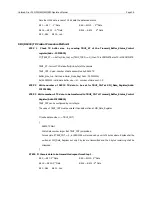
STEP 1  Check TX buffer size   by reading TBUF_ST of the Transmit_Buffer_Status_Control 

register(Addr. : F2F220Ch)   

If ((TBUF_ST == Buffer_Size_Inq) or (TBUF_TDRD ==1)) then TX is COMPLETE else TX is INCOMPLETE 


TBUF_ST : Current TX Data buffer(Unit:byte) of the camera 

TBUF_CNT : Read : Number of data transmitted by RS232 TX 

Buffer_Size_Inq : Defined in Serial_Mode_Reg( Addr. : F2F22000h) 

Ex) 20050000h : valid data buffer size = 20    number of data sent : 05 

STEP 2   Write number of RS232 TX data to be set for TBUF_CNT at SIO_Data_Register(Addr: 

F2F22100h)   

STEP 3  Write number of TX data to be transferred to TBUF_CNT of Transmit_Buffer_Status_Control 

Register(Addr:F2F2200Ch)   

TBUF_CNT can be configured by unit of byte.   

The value of TBUF_CNT must be smaller than data written at SIO_Data_Register. 


If (write data number > = TBUF_CNT) 

   RS232TX Start 

   Write Data number larger that TBUF_CNT is discarded.   

   For example if TBUF_CNT = 5 , in IEEE-1394 write is done by a unit of 4 bytes where 8 bytes shall be 

written at SIO_Data_Register but only 5 bytes are transmitted  and the 3 bytes remaining shall be 

discarded.   

STEP4    If there is data to be transmitted repeat from Step 1 .   

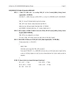
Bit 0 ~ Bit 7: 1

st

 Data    


Bit 8 ~ Bit 15: 2

nd

 Data 

Bit 16 ~ Bit 23: 3

rd

 Data 


Bit 24 ~ Bit 31: 4

th

 Data    

Bit 0 : Msb      Bit 31 : Lsb 

Summary of Contents for 530

Page 1: ...Unibrain Ultra Compact firewire cameras Models 530 550 630 830 850 User Operation Manual Version 2 0 April 2012 ...

Page 2: ...ommended in this manual must be used with this equipment in order to comply with the limits for a computing device pursuant to Subpart J of Part 15 of FCC Rules For customers in Europe This apparatus has been certified to meet or exceed the standards for CE compliance per the Council Directives Pertinent testing documentation is available for verification For customers in Canada This apparatus com...

Page 3: ...dy Warranty shall be voided for improper usage or fault caused by user or damage caused by other equipments due to negligence Warranty Unibrain warrants the original components free of defects for one year from purchase date This warranty covers failures and damage due to defect which may occur during normal use It does not cover damages or failure resulting from mishandling abuse misuse or modifi...

Page 4: ...cification 10 2 1 2 Fire i 630b Specification 11 2 1 3 Fire i 530b Specification 12 2 1 4 Fire i 550b Specification 13 2 2 Color Cameras 14 2 2 1 Fire i 830c Specification 14 2 2 2 Fire i 630c Specification 15 2 2 3 Fire i 530c Specification 16 2 2 4 Fire i 850c Specification 17 2 2 5 Fire i 550c Specification 18 2 3 Spectral Sensitivity 19 2 3 1 B W Cameras 19 2 3 2 Color Cameras 21 3 Basic Opera...

Page 5: ...tion 32 3 9 2 1 Fire i 530 630 830 32 3 9 2 2 Fire i 550 850 33 3 9 2 3 Trigger Timing Diagram for Fire i 550 850 34 3 9 2 4 Timing Diagram for External Trigger and Shutter and Strobe 35 Fire i 530 630 830 35 3 9 3 Trigger and Strobe delay 35 3 9 4 Trigger Mode 0 36 3 9 5 Trigger Mode 1 36 3 9 6 Trigger Mode 2 36 3 9 7 Trigger Mode 3 37 3 9 8 Trigger Mode 4 37 3 9 9 Trigger Mode 5 38 3 9 10 Trigge...

Page 6: ...Interface 55 4 9 1 SIO Pass Through Scheme 55 4 9 2 SIO RS232 Registers 58 4 9 3 SIO RS232 Special Commands 60 4 10 Frame Save Function 62 4 11 LUT Lookup table 63 4 11 1 4 step knee lookup table 63 4 11 2 User defined lookup table 63 4 12 One Pixel Snow Noise Remove 65 4 13 PIO Control Register 66 5 User Defined custom FIREWIRE Registers 67 5 1 User Defined FIREWIRE Address 67 6 Video Formats and...

Page 7: ...ooting 75 6 7 Hardware Related Issues 75 6 7 1 Camera is not recognized in the device manager 75 6 7 2 LED is OFF while power is provided either by FireWire or external power 75 6 7 3 No Image or Black Image is Displayed 75 7 Technical Support 76 ...

Page 8: ... 1 8 and resolution VGA XGA UXGA both in color and black and white Unibrain Bonsai camera series possess unique features that support external trigger mode 0 5 plus 14 15 multi camera auto sync one shot and multi shot a wide range of shutter speed RS232C pass through via FIREWIRETM Fast format 7 partial scan and a high speed up trigger frame rate which would provide maximum flexibility in applicat...

Page 9: ...Description Camera Body Size 29 w x 29 H x 39 D mm Camera Body Weight approx 63 gram Operation Temperature 5 C 45 C Storage Temperature 20 C 65 C Avoid operation in environment of high humidity over 90 and allow sufficient airflow for prevention of heat buildup Fire i 530 630 830 ...

Page 10: ...630 830 850 Operation Manual Page 3 Fire i 550 850 1 3 Camera Interface The camera s interface is located on the back of the camera assuming lens mount is front as per the following Trigger Connector FIREWIRETM Port Status LED ...

Page 11: ... 4 TPB 5 TPA 6 TPA CAUTION DO NOT reverse the polarity This could result in damage to the camera 1 4 1 Trigger Connector Port External Trigger Connector provides the access to multiple I O Camera Side Pin I O Signal Name 1 O TX232 2 I RX232 3 X NC 4 O Strobe 5 I Ext Trigger 6 I GND Note NC pins must have no connection 1 4 2 Status LED LED Status Isochronous channel Packet Transfer RED Disable NO G...

Page 12: ... 5 Electrical Operating Condition Trigger Recommended Trigger Example 1 Recommended Trigger Example 2 Electrical Specification User Side Trigger Opto Coupler Camera Side External_ Trigger Pin GND Pin Recommended Trigger Exampl e Ext Trigger signal Ext trigger GND ...

Page 13: ...ommended Strobe Example 1 Recommended Strobe Example 2 Electrical Specification User Side Strobe Opto Couple r Came ra Sid e Strobe Pi n Active Hig h GND Pin GND 220 Ω Recommended St robe Exampl Strobe signal Strobe GND App 2msec User can set strobe duration Strobe 4V 5V ...

Page 14: ...all be set to zero channel isochronous channel number as programmed in the iso_channel field of the cam_sta_ctrl register tCode transaction code shall be set to the isochronous data block packet tCode sy synchronization value shall be set to 0001h on the first isochronous data block of a frame and shall be set to zero on all other isochronous data blocks Video data payload shall contain the digita...

Page 15: ...t Y K 0 Y K 1 Y K 2 Y K 3 Y K 4 Y K 5 Y K 6 Y K 7 Y K Pn 8 Y K Pn 7 Y K Pn 6 Y K Pn 5 Y K Pn 4 V K Pn 3 Y K Pn 2 Y K Pn 1 Y Mono Format High Byte Low Byte Y K 0 Y K 1 Y K 2 Y K 3 Y K Pn 4 Y K Pn 3 V K Pn 2 Y K Pn 1 Data Structure Y R G B ach component has 8 bit data The data type is Unsigned Char Signal Level Decimal Data Hexadecimal Highest 255 0xFF 254 0xFE 1 0x01 Lowest 0 0x00 ...

Page 16: ... Straight Binary Signal Level Decimal Data Hexadecimal Highest 127 0xFF 126 0xFE 1 0x81 Lowest 0 0x80 1 0x7F 127 0x01 Lowest 128 0x00 Y Mono16 Y component has 16 bit data The data type is Unsigned Short big endian Y Signal Level Decimal Data Hexadecimal Highest 65535 0xFFFF 65534 0xFFFE 1 0x0001 Lowest 0 0x0000 ...

Page 17: ...3 4 5 14 15 Source External Trigger or Software Trigger Strobe Active High Support Normal Mode or Trigger Mode Multi camera auto sync 144 us 144 us at 15 7 5 frame rate Memory Save Load 16 Channels 0 factory 1 4 feature 5 15 mode feature One shot Multi shot 65535 Shots Control Functions Brightness Sharpness Gamma Auto Exposure Shutter Gain Pan Tilt High speed up trigger frame rate SIO RS 232 IIDC ...

Page 18: ...are Trigger Strobe Active High Support Normal Mode or Trigger Mode Multi camera auto sync 144 us 144 us at 30 15 7 5 frame rate Memory Save Load 16 Channels 0 factory 1 4 feature 5 15 mode feature One shot Multi shot 65535 Shots Control Functions Brightness Sharpness Gamma Auto Exposure Shutter Gain Pan Tilt High speed up trigger frame rate SIO RS 232 IIDC v1 31 version Path through or custom comm...

Page 19: ...er Strobe Active High Support Normal Mode or Trigger Mode Multi camera auto sync 144 us 144 us at 60 30 15 7 5 frame rate Memory Save Load 16 Channels 0 factory 1 4 feature 5 15 mode feature One shot Multi shot 65535 Shots Control Functions Brightness Sharpness Gamma Auto Exposure Shutter Gain Pan Tilt High speed up trigger frame rate SIO RS 232 IIDC v1 31 version Path through or custom command Fr...

Page 20: ... Strobe Active High Support Normal Mode or Trigger Mode Multi camera auto sync Not supported Memory Save Load 16 Channels 0 factory 1 4 feature 5 15 mode feature One shot Multi shot Not supported Control Functions Brightness Sharpness Gamma Auto Exposure Shutter Gain Pan Tilt SIO RS 232 IIDC v1 31 version Path through or custom command Frame Delay from Read out Min 70us Digital Interface Transfer ...

Page 21: ...Source External Trigger or Software Trigger Strobe Active High Support Normal Mode or Trigger Mode Multi camera auto sync 144 us 144 us at 15 7 5 frame rate Memory Save Load 16 Channels 0 factory 1 4 feature 5 15 mode feature One shot Multi shot 65535 Shots Control Functions Brightness Sharpness Gamma Auto Exposure Shutter Gain Pan Tilt High speed up trigger frame rate AWB SIO RS 232 IIDC v1 31 ve...

Page 22: ...pport Normal Mode or Trigger Mode Multi camera auto sync 144 us 144 us at 30 15 7 5 frame rate Memory Save Load 16 Channels 0 factory 1 4 feature 5 15 mode feature One shot Multi shot 65535 Shots Control Functions Brightness Sharpness Gamma Auto Exposure Shutter Gain Pan Tilt High speed up trigger frame rate AWB SIO RS 232 IIDC v1 31 version Path through or custom command Frame Delay from Read out...

Page 23: ...al Mode or Trigger Mode Multi camera auto sync 144 us 144 us at 60 30 15 7 5 frame rate Memory Save Load 16 Channels 0 factory 1 4 feature 5 15 mode feature One shot Multi shot 65535 Shots Control Functions Brightness Sharpness Gamma Auto Exposure Shutter Gain Pan Tilt High speed up trigger frame rate AWB SIO RS 232 IIDC v1 31 version Path through or custom command Frame Delay from Read out Min 43...

Page 24: ...ger Strobe Active High Support Normal Mode or Trigger Mode Multi camera auto sync Not supported Memory Save Load 16 Channels 0 factory 1 4 feature 5 15 mode feature One shot Multi shot Not supported Control Functions Brightness Sharpness Gamma Auto Exposure Shutter Gain Pan Tilt High speed up trigger frame rate AWB SIO RS 232 IIDC v1 31 version Path through or custom command Frame Delay from Read ...

Page 25: ...ctive High Support Normal Mode or Trigger Mode Multi camera auto sync Not supported Memory Save Load 16 Channels 0 factory 1 4 feature 5 15 mode feature One shot Multi shot Not supported Control Functions Brightness Sharpness Gamma Auto Exposure Shutter Gain Pan Tilt High speed up trigger frame rate AWB SIO RS 232 IIDC v1 31 version Path through or custom command Frame Delay from Read out Min 70us...

Page 26: ...re i 530 550 630 830 850 Operation Manual Page 19 2 3 Spectral Sensitivity Excludes lens and light source characteristics 2 3 1 B W Cameras Spectral Sensitivity for Fire i 830b Spectral Sensitivity for Fire i 630b ...

Page 27: ...Unibrain Fire i 530 550 630 830 850 Operation Manual Page 20 Spectral Sensitivity for Fire i 530b Spectral Sensitivity for Fire i 550b ...

Page 28: ...Unibrain Fire i 530 550 630 830 850 Operation Manual Page 21 2 3 2 Color Cameras Spectral Sensitivity for Fire i 830c Spectral Sensitivity for Fire i 630c ...

Page 29: ...Unibrain Fire i 530 550 630 830 850 Operation Manual Page 22 Spectral Sensitivity for Fire i 530c Spectral Sensitivity for Fire i 850c ...

Page 30: ...Unibrain Fire i 530 550 630 830 850 Operation Manual Page 23 Spectral Sensitivity for Fire i 550c ...

Page 31: ...not be obtained due to blurring of black portions of the image The parameters of Brightness are changed inside the camera For brightness the parameters are shifted by the black level 4095 0 4095 Inquiry Register Address Name Field Bit Description 500h BRIGHTN ESS_INQ Presence_Inq 0 Presence of this feature Abs_Control_Inq 1 Capability of control with absolute value 2 Reserved One_Push_Inq 3 One pu...

Page 32: ... to Contrast Control Inquiry Register Address Name Field Bit Description 504h AUTO_EXP OSURE_INQ Presence_Inq 0 Presence of this feature Abs_Control_Inq 1 Capability of control with absolute value 2 Reserved One_Push_Inq 3 One push auto mode Controlled automatically by camera only once ReadOut_Inq 4 Capability of reading the value of this feature On Off_Inq 5 Capability of switching this feature O...

Page 33: ... which can be controlled automatically or manually U R Red Green and V B Green Blue alter the degree to which Red and Blue CCD component pixels are weighed to form composite pixels In manual mode you can adjust the white balance by altering the Blue U V and Red Value V R In addition the one push white balance option can be used for a non interactive calibration Inquiry Register Address Name Field ...

Page 34: ...the mode Read read a current mode 0 Manual 1 Auto 8 19 U Value B_Value Write the value in AUTO mode this field is ignored If ReadOut capability is not available read value has no mean Value 20 31 V Value R_Value Write the value in AUTO mode this field is ignored If ReadOut capability is not available read value has no meaning 3 5 Hue Color models support Hue control which changes the color phase o...

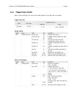
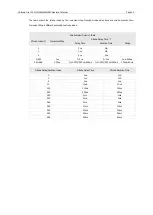
Page 35: ...hutter is defined as the integration time of the incoming light where both the Manual and the Auto Shutter are supported The shutter range varies from 1us 3600sec For Shutter control inquiry and status register follow the same definition as BRIGHTNESS 3 7 1 1 Fire i x3x models 530 630 830 Shutter Speed Value Range 1394 Shutter Value Y Increment Step Shutter Speed Time T Exposure Time Range 1 500 1...

Page 36: ...422 1s 3525 7min 550 1ms 2522 2s 3543 10 min 650 2ms 2822 5s 3603 20 min 950 5ms 2944 10s 3663 30 min 1045 10ms 3044 20s 3723 40 min 1145 20ms 3318 60s 3783 50 min 1445 50ms 3323 65s 3843 60 min 3 7 1 2 Fire i x5x models 550 850 Shutter Speed Value Range 1394 Shutter Value Y Increment Step Shutter Speed Time T Exposure Time Range 1 500 1us T Y us 1us 500us 501 1000 10us T Y 500 10 500 us 510us 550...

Page 37: ...odels 550 850 Camera Type Step Range Range in dB Increment Length Fire i 550 b c 16 64 0 12 16 31 20 x Log step x 0 0625 32 64 20 x Log step 2 x 0 0625 Fire i 850c 0 63 Digital gain 3 9 Trigger Strobe The cameras support external trigger by receiving input through the external trigger port The falling edge and rising edge can be detected as a trigger according to the modes it supports as per the f...

Page 38: ...Presence of Trigger Mode3 20 31 Reserved Status Control Register Address Name Field Bit Description 830h TRIGGER_ MODE Presence_Inq 0 Presence of this feature 0 N A 1 Available Abs_Control 1 Absolute value control 0 Control with value in the Value field 1 Control with value in the Absolute value CSR If this bit 1 value in the Value field is ignored 2 5 Reserved ON_OFF 6 Write ON or OFF this featur...

Page 39: ...Unibrain Fire i 530 550 630 830 850 Operation Manual Page 32 3 9 2 Trigger and Strobe Signal Relation 3 9 2 1 Fire i 530 630 830 ...

Page 40: ...Unibrain Fire i 530 550 630 830 850 Operation Manual Page 33 3 9 2 2 Fire i 550 850 ...

Page 41: ...er delay 350ns Exposure Time 7HD 640 x 480 60fps 1VD 30fps 2VD 15fps 4VD 7 5fps 8VD 3 75fps 16VD 752 x 480 Format 7 1VD Fire i 850 Trigger Mask Trigger delay 250ns Exposure Time 29 HD 640 x 480 60fps 1VD 30fps 2VD 15fps 4VD 7 5fps 8VD 3 75fps 16VD 800 x 600 30fps 1 VD 15fps 2 VD 7 5fps 4 VD 3 75fps 8 VD 1024 x 768 15fps 1 VD 1280 x 960 7 5fps 2 VD 1600 x 1200 3 75fps 4 VD 2048 x 1536 Format 7 1VD ...

Page 42: ... and Shutter and Strobe Fire i 530 630 830 This diagram shows the necessary time related to each signal for External trigger and Shutter and Strobe 3 9 3 Trigger and Strobe delay The starting point for the Strobe signal is the same as the Starting point for the External trigger Fire i 530 550 630 830 850 ...

Page 43: ...de 1 The camera starts the integration of the incoming light from the external trigger input falling edge The integration time is equal to the low state time of the external trigger input No parameter is needed 3 9 6 Trigger Mode 2 The camera starts the integration of incoming light from the first external trigger input falling edge At the N th parameter external trigger input falling edge the int...

Page 44: ...of the incoming light is described in the Shutter register A Parameter is required and shall be one or more N 1 3 9 8 Trigger Mode 4 This mode is the multiple shutter preset mode The camera starts the integration of the incoming light from the first external trigger input falling edge and exposes the incoming light at shutter time Repeat this sequence for the N th parameter external trigger input ...

Page 45: ...single trigger This mode is Similar to trigger mode 4 but the difference is that all the parameters are preset by the users using only a single trigger Exposure Number Exposure Duration and Exposure Interval are the parameters required for this mode However the exposure duration and interval in each multiple shutter is equal and cannot be different Exposure duration interval is defined by a user d...

Page 46: ...Unibrain Fire i 530 550 630 830 850 Operation Manual Page 39 ...

Page 47: ... function ON and OFF Polarity_Inq 6 Capability of changing polarity of the signal 7 Reserved Min_Value 8 19 Minimum value of this function control Max_Value 20 31 Maximum value of this function control 104h Strobe_1_Inq Same definition to Strobe_0_Inq Strobe_2_Inq Same definition to Strobe_1_Inq Strobe_3_Inq Same definition to Strobe_2_Inq 110h 1FCh Reserved 200h Strobe_0_Cnt Presence_Inq 0 Presen...

Page 48: ... of exposure until the strobe signal asserts Duration_Value 20 31 Duration of the strobe signal A value 0 means dessert at the end of exposure function if required 204h Strobe_1_Cnt Same definition to Strobe_0_Inq 208h Strobe_2_Cnt Same definition to Strobe_1_Inq 20Ch Strobe_3_Cnt Same definition to Strobe_2_Inq 210h 2FFh Reserved ...

Page 49: ...y of reading the value of this feature On OFF_Inq 5 Capability of switching this feature ON and OFF Auto_Inq 6 Auto Mode Controlled automatically by camera Manual_Inq 7 Manual Mode Controlled by user Min_Value 8 19 Minimum value for this feature control Max_Value 20 31 Maximum value for this feature control Status Control Register Address Name Field Bit Description 834h TRIGGER_DELAY Presence_Inq ...

Page 50: ...ble Strobe Index Y Increment Step Strobe Delay Time T Delay Time Duration Time Range 0 0us N A 1 1us N A 2 2us 2us 3 250 1us T Y us T Y us 3us 250us 251 489 250us T Y 250 250us 250us T Y 250 250us 250us 500us 60ms Strobe Delay Duration Index Strobe Delay Time Strobe Duration Time 0 0us N A 1 1us N A 2 2us 2us 10 10us 10us 100 100us 100us 250 250us 250us 253 1ms 1ms 257 2ms 2ms 269 5ms 5ms 289 10ms...

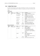
Page 51: ...ility of reading the value of this feature On OFF_Inq 5 Capability of switching this feature ON and OFF Auto_Inq 6 Auto Mode Controlled automatically by camera Manual_Inq 7 Manual Mode Controlled by user Min_Value 8 19 Minimum value for this feature control Max_Value 20 31 Maximum value for this feature control Status Control Register Address Name Field Bit Description 88Ch OPTICAL_FILTER Presence...

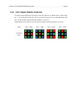
Page 52: ...ged data is transferred to the PC where the color processing can save bandwidth gaining higher frame rate and flexibility of applying different Bayer Patterns on the PC side Obtained Images can be processed in any of the following 4 different conversion algorithms on the PC side Modes Mode 0 GB RG Mode 1 BG GR Mode 2 RG GB Mode 3 GR BG Color Bayer Pattern G R R G G G G B B B G G B R B B G G R G G ...

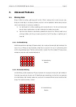
Page 53: ...ng in a significant gain in frame rate 4 1 1 Vertical Binning Vertical binning combines neighboring CCD pixels vertically into a single pixel increasing the light sensitivity of the camera Since a CCD acquires data horizontally multiple lines are acquired in the case of vertical binning which results in a significant speed gain Thus the vertical resolution is reduced Due to the increased CCD area ...

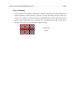
Page 54: ...tical conjunction of these pixels This would increase light sensitivity by a factor of 4 in the case of 2 x 2 Horizontal x Vertical binning However as described above only vertical binning would result in a speed gain while horizontal binning gives no speed gain Thus the speed gain result is similar to vertical binning Resolution in this mode would be reduced both horizontally and vertically 2x2 F...

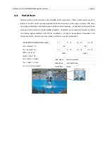
Page 55: ...ed gain would occur only if vertical resolution decreases Partial Scan is only supported in Format 7 by setting the following registers described in the IIDC1 31 specification Unit size of the partial scan is described in the camera specification which the user must consider in setting the increment configuration IMAGE POSITION IMAGE SIZE register Left Hposunit n1 Top Vposunit m1 Width Hunit n2 He...

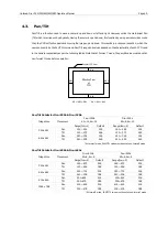
Page 56: ...sical CCD Pixel Effective Pixel of CCD Kh Kh1 Kh2 Kv Kv1 Kv2 Pan Tilt Details for Fire i 530b Fire i 530b Image Size Movement Fire i 530b Kh 12 Kv 12 Fire i 530c Kh 8 Kv 10 Range Incr 1 Default Range Incr 2 Default 320 x 240 Pan 160 492 326 160 488 324 Tilt 120 372 246 120 370 242 640 x 480 Pan 320 332 326 320 328 324 Tilt 240 252 246 240 250 242 At format7 mode PAN TITL value must be set at non f...

Page 57: ... 616 120 1114 616 640 x 480 Pan 320 1302 810 320 1300 810 Tilt 240 994 616 240 994 616 800 x 600 Pan 400 1222 810 400 1220 810 Tilt 300 934 616 300 934 616 1024 x 768 Pan 512 1110 810 512 1108 810 Tilt 384 850 616 384 850 616 1280 x 960 Pan 640 982 810 640 980 810 Tilt 480 754 616 480 754 616 1600 x 1200 Pan 800 822 810 800 820 810 Tilt 600 634 616 600 634 616 1600 x 1200 Format 7 Mode 0 Pan Tilt ...

Page 58: ...ger which grabs either one frame or multi frames according to the respective command The command can be executed configuring the following registers Caution One Shot and Multi Shots are not supported in trigger mode One Shot Multi Shot Address F0F0061CH Address F0F0061CH Data 80000000h Data 4000nnnh nnnn is the number of output frames which can be any number between 0001h FFFFh 1 65 535 Priority o...

Page 59: ...re i 850 models FPS Fire i 530x Fire i 630x Fire i 830x Max Shutter Max Shutter Max Shutter Value Time Value Time Value Time 60 1110 16 5ms 30 1276 33 1ms 1270 32 5ms 15 1608 66 3ms 1598 65 3ms 1606 66 1ms 7 5 1760 131ms 1758 129ms 1760 131ms 3 75 1893 264ms 1889 260ms 1893 264ms To utilize Auto sync please set Bit 31 to Auto sync Enable and then check the Bit 27 to verify whether it is ready Plea...

Page 60: ...ing 1 31 Reserved Address Name Bit Description 620h Mem_Save_Ch 0 Factory Default Setting Cannot overwrite 1 4 Write Channel for Memory Save for Channel 1 4 Only for Features 5 15 Write Channel for Memory Save for Channel 5 15 For Features Format and Mode Save Address Name Bit Description 624h Cur_Save_Ch 0 Read and Load Factory Default Setting 1 4 Read and Load Memory Channel 1 4 5 15 Read and Lo...

Page 61: ... but we recommend this Address Description bit msb Read Write 0xF0000200 CYCLE_TIME 0 1 2 3 4 5 6 7 8 9 10 11 12 13 14 15 16 17 18 19 20 21 22 23 24 25 26 27 28 29 30 31 SECONDS COUNT CYCLE COUNT CYCLE OFFSET Bit Numbe r Bit Nam e Function DIR Description 0 6 7 19 20 31 SECONDS COUNT CYCLE COUNT CYCLE OFFSET Seconds Coun t Cycle Coun t Cycle Offset R W R W R W 1 Hz c ycle timer counte r 8 000 Hz c...

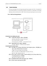
Page 62: ... Parity 1 bit Stop 8 bit data length Write F2F22000h Data 050800000h Value read after write 050800020h 20 is the buffer of TX and RX STEP 2 Enable RS232 TX RX Address F2F22004h Write Data C00000000 Now RS232 TX RX port is enabled SIO RS232 RX Control Procedure STEP 1 Read RBUF_ST of the Receive Buffer Status Control Register address F2F22008h and check number of RX data buffered in the camera If R...

Page 63: ...id data buffer size 20 number of data sent 05 STEP 2 Write number of RS232 TX data to be set for TBUF_CNT at SIO_Data_Register Addr F2F22100h STEP 3 Write number of TX data to be transferred to TBUF_CNT of Transmit_Buffer_Status_Control Register Addr F2F2200Ch TBUF_CNT can be configured by unit of byte The value of TBUF_CNT must be smaller than data written at SIO_Data_Register If write data numbe...

Page 64: ... data to be set for TBUF_CNT at Transmit_Buffer_Status_Control Register Addr F2F2200Ch TBUF_CNT can be configured by unit of byte The value of TBUF_CNT must be smaller than data written at SIO_Data_Register STEP 3 Write RS232 TX data set at TBUF_CNT to SIO_Data Register Addr F2F22100h If write data number TBUF_CNT RS232TX Start Write Data number larger that TBUF_CNT is discarded For example if TBU...

Page 65: ...et current parity 0 None 1 Odd 2 Even Stop_bit 18 19 Stop bits Write Set stop bit Read Get current stop bit 0 1 1 1 5 2 2 20 23 Reserved Buffer_Size_Inq 24 31 Buffer Size Read Only This field indicates the maximum size of receive transmit data buffer If this value 1 Buffer_Status_Control SIO_Data_Register Char1 3 should be ignored 004h Serial_Control_Reg RE 0 Receive enable Read Current status Wri...

Page 66: ...t data size for transmit 16 31 Reserved 010h 0FFh Reserved 100h SIO_Data_Register Char_0 0 7 Chracter_0 Read Read character from receive buffer Padding data if data is not available Write Character to transmit buffer padding data if data is invalid Char_1 8 15 Chracter_1 Read Read character from receive buffer 1 Padding data if data is not available Write Character to transmit buffer 1 padding dat...

Page 67: ...e Gdd d dd d is return data and hexadecimal character U Undefined command Valid Character 0 9 A F S Z Invalid character is received is discarded Example Gain setting command with 0x200 value All of SA0200Z S A0 200 Z SA0 200Z S A0200 Z and SKA0V200Z are parsed to SA0200Z Z and SKA0V200Z are parsed to SA0200Z SIO RS232 Commands STX Command Data Length ETX Return Value Function S A0 3Bytes Z G Gain ...

Page 68: ... S B0 16Bytes Z G RS232 synchronization RS232 buffer cleared in camera S B1 8Bytes Z G Write access of 1394 address Format SB1 address 8 byte data 8byte Z Ex SB1F2F1010012345678Z write 0x12345678 data at 0xF2F10100 address S B2 0Bytes Z G 8 Byte Read access of 1394 address Format SB2 address 8byte Z Ex If command is SB2F2F10100Z and return value is G12345678 Read value of address 0xF2F10100 is 0x1...

Page 69: ...emory Max savable frame numbers are different according to models The saved images are useful for multi cameras applications IEEE1394 images are transferred by the ISO channel and 400Mbps is the max bandwidth of maximum save frames address 0xF2F10128 bit 16 bit 23 read value Resolution Mode 800 Mode 1600 Y422 640 x 480 63 frames 31 frames 800 x 600 63 frames 31 frames 1024 x 768 31 frames 15 frame...

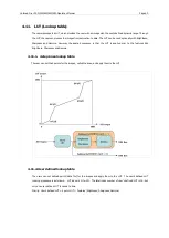
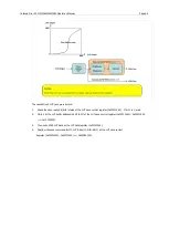
Page 70: ...the LUT is applied prior to the features like Brightness Sharpness and Gamma 4 11 1 4 step knee lookup table The user can set the 4 points for the images called the knee and apply them to the LUT 4 11 2 User defined lookup table The users can set defined points data file for the images and apply them to the LUT The user s defined LUT running procedure is as follows LUT index is N o 15 The total in...

Page 71: ...ave control register 0xF2F10140 If bit 1 is 0 wait 2 Write 1 at the LUT buffer address init bit bit7 of the LUT save control register 0xF2F10140 0xF2F10140 0x01000000 3 Then write 4096 LUT data at the LUT data register 0xF2F10144 4 Finally write save command bit0 LUT index N bit8 bit11 at the LUT save control Register 0xF2F10140 0xF2F10140 0x80N00000 ...

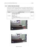
Page 72: ...increase the average pixels values for the whole image and be automatically displayed and the images can be compensated by over up to 50 The register address and values for this function are Address Description bit 0 msb Read Write 0xF2F20150 One Pixel Snow Noise Remove Bit 0 presence inquiry read only Bit 1 Bit 5 reserved Bit 6 on off Bit 7 Bit23 reserved Bit 24 Bit31 Threshold Value T If Pixel d...

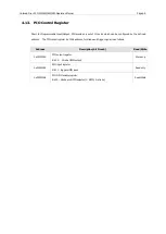
Page 73: ... by the defined address The PIO control register by 1394 address for strobe and trigger signal is as follows Address Description bit 0 msb Read Write 0xF2F21000 PIO output register Bit 30 Strobe GPIO output Write only 0xF2F21004 PIO input register Bit 31 trigger GPIO input Read only 0xF2F21008 PIO GPIO enable register Bit 30 Strobe pin GPIO selector 1 GPIO 0 strobe Read Write ...

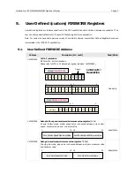
Page 74: ...ution Please refer to IIDC v1 31 data depth register address 0xF0F00630 Read only 0xF2F10004 Auto shutter speed maximum minimum value register 32bit At auto shutter mode shutter speed value is checked between auto shutter speed maximum value and minimum value Auto Shutter Speed Maximum Value Auto Shutter Speed Minimum Value 0 15 16 31 Read Write 0xF2F10008 Auto gain maximum minimum value register ...

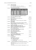
Page 75: ...ad Write 0xF2F10184 Local ISO_EN control register for one shot multi shot Bit 31 iso_enable 1 enable 0 disable 0xF2F1011C Power on default memory channel Bit 0 Bit 3 power on initial memory channel Read Write 0xF2F10200 Camera version register Bit 16 Bit 31 camera version ex If reading value 0x00003000 camera version is 3 000 Read only 0xF2F10120 Bright Level for Iris Control Application Bit 24 Bi...

Page 76: ... 8 Bit 19 X coordination of 3rd knee point Bit 20 Bit31 Y coordination of 3rd knee point Read Write 0xF2F10138 LUT knee 4th point register Bit 0 presence inquiry read only Bit 1 LUT regeneration command self cleared Bit 2 Bit5 reserved Bit 6 reserved Bit 7 reserved Bit 8 Bit 19 X coordination of 4th knee point Bit 20 Bit31 Y coordination of 4th knee point Read Write 0xF2F1013C User defined LUT run...

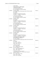
Page 77: ...able Bit 8 Bit23 reserved Bit 24 Bit31 Threshold Value T If Pixel difference value Threshold Value the pixel is replaced with near pixel average value Read Write 0xF2F10168 Another sharpness Bit 0 presence inquiry read only Bit 1 Bit5 reserved Bit 6 On Off Bit 7 reserved Bit 8 Bit 23 reserved Bit 24 Bit 31 sharpness value 10 normal range 5 20 Read Write msb most significant bit Threshold Value T 0...

Page 78: ...rmat 7 to meet this demand Format 7 is extremely flexible and allows the user to define the width height position and pixel format of the video data where separate sets of control registers exists for each Format 7 mode The cameras support Format 7 modes 0 1 2 with the following base address Format 7 Mode 0 F1F00000h Format 7 Mode 1 F1F00100h Format 7 Mode 0 F1F00200h Offset Name Description 000h ...

Page 79: ...x 600 RGB 8 2 800 x 600 Mono 8 O O 3 1024 x 768 YUV 422 O O O O 4 1024 x 768 RGB 8 5 1024 x 768 Mono 8 O O O O 6 800 x 600 Mono 16 O O O 7 1024 x 768 Mono 16 O O O O 2 0 1280 x 960 YUV 422 O O O 1 1280 x 960 RGB 8 2 1280 x 960 Mono 8 O O O O 3 1600 x 1200 YUV 422 O O O 4 1600 x 1200 RGB 8 5 1600 x 1200 Mono 8 O O O O 6 1280 x 960 Mono 16 O O O 7 1600 x 1200 Mono 16 O O O 7 0 1600 x 1200 16 fps Max...

Page 80: ...6 O O O O 7 1024 x 768 Mono 16 O O O O 7 0 1024 x 768 30 fps Max at Mono 8 Frame rate may differ in YUV Mono 16 and Bayer 1 512x384 58 512x384 Format7 mode1 2x2 binning B W only 2 1024x384 58 1024x384 Format7 mode2 1x2 binning B W only 6 3 Fire i 530b Fire i 530c Format Mode Resolution 60fps 30fps 15fps 7 5fps 3 75fps 1 875fps 0 0 160 x 120 YUV 444 1 320 x 240 YUV 422 2 640 x 480 YUV 411 3 640 x 4...

Page 81: ...280 x 960 Mono 8 O O O 3 1600 x 1200 YUV 422 O O 5 1600 x 1200 Mono 8 O O O 6 1280 x 960 Mono 16 O O 7 1600 x 1200 Mono 16 O O 7 0 2048 x 1536 10 fps Max at Mono 8 Frame rate may differ in YUV Mono 16 and Bayer 1 1024 x 768 26 fps Max at Mono 8 Frame rate may differ in YUV Mono 16 and Bayer 6 5 Fire i 550b Fire i 550c Format Mode Resolution 60fps 30fps 15fps 7 5fps 3 75fps 1 875fps 0 3 640 x 480 Y...

Page 82: ... camera connection Please check the cable connection on both the camera and the PC The LED status when plugging in the camera is supposed to be normal when the LED light changes from an Orange light to a Red light If you haven t installed the camera driver yet please refer to the software installation manual and install the drivers and software provided Please reconnect the camera by plugging the ...

Page 83: ...case you require technical support contact the agent near you or may contact us directly at the following locations Web information specifications FAQs http www unibrain com Technical support email support unibrain com Sales inquiries sales unibrain com Telephone Numbers Europe Asia 30210 6640600 USA Canada South America 1 925 866 3000 In case of RMA you must first contact us or your local reselle...

Reviews: