background image

2

3

P/N

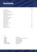
Contents

Page

4
5

7

8
9

10

11

12
13
14
15
16

1

8

20
21

2

2

24

Intended Use
General Safety Rules 
Information Plate Symbols 
Specification
Operational


Safety Procedures


Operating Instructions 
Control Panel
Extension Cable Selection 
Mounting Of Cutters

Tr

oubleshooting

Wiring Diagram
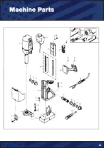
Machine Parts
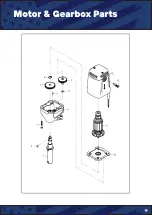
Motor & Gearbox Parts

P

ipe Adapter

Fitting the Chuck


Maintenance
Warranty Statements

RD4329 

Safety Strap

RD4088 

4mm A/F Tee Handled Hexagon Key

RD4152 

3mm Hexagon Key

RD33153 

Drill Chuck Adaptor

RD4230 

6mm Hexagon Key

RD43099 

Drill Chuck and key

RDA3067/1 (110V)

Carbon brush

RDA 3067/3 (230V) 

Carbon brush

Summary of Contents for E3000

Page 1: ...1 Magnetic Drilling Machine WWW UNIBORUSA COM This machine is CSA approved Model Number E3000 V1...

Page 2: ...2...

Page 3: ...Panel Extension Cable Selection Mounting Of Cutters Troubleshooting Wiring Diagram Machine Parts Motor Gearbox Parts Pipe Adapter Fitting the Chuck Maintenance Warranty Statements RD4329 Safety Strap...

Page 4: ...metals The magnet is used to hold the drill in place whilst the drill is functioning It is designed for use in fabrica tion construction railways petrochemical and any other applications when drillin...

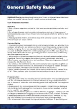
Page 5: ...is grounded 3 Don t expose power tools to rain or wet conditions Water entering a power tool will increase the risk of electric shock 4 Do not abuse the cord Never use the cord to carry the tools or...

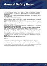
Page 6: ...users 6 Maintain tools with care Keep cutting tools sharp and clean Properly maintained tools with sharp cutting edges are less likely to bind and are easier to control 7 Check for misalignment or bi...

Page 7: ...r manual for operational and safety issues with regards to this machine 2 Dispose of the machine and electrical components correctly 3 Eye protection must be worn when operating the machine 4 Ear defe...

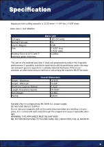
Page 8: ...nit Voltages 120V 50 60Hz Normal Full Load 7A Electro Magnet 57W Size 7 3 32 long 3 9 16 wide Holding Force at 20 C with 1 minimum plate thickness 2248lbs The use on any material less than 1 thick wil...

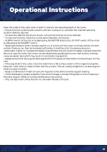
Page 9: ...rotected when changing cutters or removing swarf Use a tool or brush where necessary to remove any swarf or the cutter from the arbor Before operating the machine ALWAYS ensure cutter retaining screws...

Page 10: ...esirable it does not increase the speed of penetration and will cause the safety overload protection device to stop the motor the motor can be restarted by operating the motor start button and may cau...

Page 11: ...11 s Control Panel...

Page 12: ...urce care must be taken in using a cable of adequate capacity Failure to do so will result in a loss of traction by the magnet and a reduction of power from the motor Assuming a normal AC supply of th...

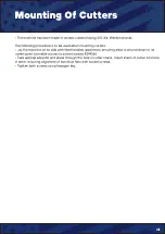
Page 13: ...ters Lay the machine on its side with feed handles uppermost ensuring arbor is wound down to its lowest point to enable access to socket screws RD4066 Take appropriate pilot and place through the hole...

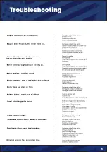
Page 14: ...irty or damaged Bottom of magnet not clean and dry Bottom of magnet not flat Work piece is not bare metal Work piece is not flat Work piece is too thin less than 3 5mm Defective control unit Defective...

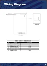
Page 15: ...15 s Wiring Diagram...

Page 16: ...16 s Machine Parts...

Page 17: ...17 s Machine Parts...

Page 18: ...18 s Motor Gearbox Parts...

Page 19: ...19 s Motor Gearbox Parts...

Page 20: ...n line with the longitudinal axis of the pipe Switch on the magnet and move the sliding plates down to the outside diameter of the pipe Tighten the screws on both sides by hand then check once again t...

Page 21: ...the two grub screws at the top of the arbor When the arbor has become detached from the spindle this can then be removed Remove the arbor support bracket and guard with the arbor retained Mount the ch...

Page 22: ...Check alignment of the machine Check grease Check armature Visually check the machine for damage The machine must be checked before operation for any signs of damage that will affect the operation of...

Page 23: ...ny further necessary adjustments Try to ensure that all the screws are exerting a uniform pressure on the slide from top to bottom A perfectly adjusted slide will operate freely up and down without an...

Page 24: ...oad or insufficient servicing or maintenance 3 Defects caused by using accessories components or spare parts other than original Unibor parts 4 Tools to which changes or additions have been made 5 Ele...

Page 25: ...25 s Extra...

Page 26: ...26 s Extra...

Page 27: ...27 s Extra...

Page 28: ...28 s Extra...

Page 29: ...29 s Extra...

Page 30: ...30 s Extra...

Page 31: ...32 WWW UNIBORUSA COM This machine is CSA approved...

Reviews: