background image


OPERATING AND MAINTENANCE MANUAL CROSS S 


- 4 - 


Table of contents 

PREFACE: ................................................................................................................................................. 6 

1.  Precautions .................................................................................................................................. 6 

1.1.  Before you Begin to Use Your Machine............................................................................... 6 
1.2.  Health and safety regulations ............................................................................................. 6 
1.3.  Servicing .............................................................................................................................. 7 
1.4.  Transport on highways ........................................................................................................ 7 
1.5.  Safety Symbol ...................................................................................................................... 8 
1.6.  Nameplate ........................................................................................................................... 9 

2.  Technical and Identification Data .............................................................................................. 10 

2.1. CROSS Specifications .............................................................................................................. 11 

3.  Operating Manual ..................................................................................................................... 12 

3.1.  First Start ........................................................................................................................... 12 
3.2.  Preparation of the Unit (T Machine) .................................................................... 12 
3.3.  Mounting and Disconnection of machines ........................................................................ 13 

3.3.1. 

Mounted machines ................................................................................................... 13 

3.3.2. 

Semi-mounted machines .......................................................................................... 14 

3.4.  Access to the Field – Transport ......................................................................................... 15 

3.4.1 

Mounted machines ................................................................................................... 15 

3.4.2 

Semi-mounted machines .......................................................................................... 16 

3.5.  Adjustment of the Cultivator ............................................................................................. 17 

3.5.1. 

Working Depth Adjustment - Cross .......................................................................... 17 

3.5.2. 

Adjustment of the Working Depth of the Disc Harrow Type A ................................. 18 

3.5.3. 

 Extreme Disc Adjustment in the Cross Harrow Type A ............................................ 18 

3.5.4. 

Heavy-Duty Tine, Type CX ......................................................................................... 19 

3.5.5.Working Depth Adjustment in the Cross Drive ................................................................ 20 
3.5.6. 

Working Depth Adjustment on the Drawbar in the Cross Drive ............................... 20 

3.5.7. 

Working Depth Adjustment on the Support Wheel in the Cross DRIVE (Option) .... 21 

3.5.8. 

Adjustment of Scraping Disc Harrow Type A in the Cross DRIVE .............................. 22 

3.5.9. 

Adjustment of Scraping Disc Harrow Type B in the Cross DRIVE .............................. 22 

3.5.10.  Adjustment of Extreme Disc Type B in the Cross DRIVE ........................................... 23 

4.  Operation (see par. II Safety) .................................................................................................... 24 
5.  Servicing and Maintenance ....................................................................................................... 24 

Summary of Contents for CROSS S

Page 1: ......

Page 2: ......

Page 3: ...21 2008 Journal of Laws No 199 item 1228 and the EU Directive 2006 42 EC of May 17 2006 and the Ordinance of the Minister of Infrastructure of May 4 2009 Journal of Laws No 75 2009 item 639 and the following standards PN EN ISO 12100 2012 PN EN ISO 13857 2010 PN ISO 3600 1998 PN EN ISO 4413 2011 PN ISO 11684 1998 PN EN 349 A1 2010 PN EN ISO 11688 1 2010 PN EN 14017 A2 2009 PN EN ISO 4254 1 2016 02...

Page 4: ......

Page 5: ...ction year Serial no This maintenance and operating manual is an integral part of the machine It is important that the manual is always in the possession of the machine user Access to the manual should be provided to machine operators and cooperating persons while operation regulation repairs and renovations Before starting the machine please read the operating manual and follow the recommendation...

Page 6: ...nted machines 15 3 4 2 Semi mounted machines 16 3 5 Adjustment of the Cultivator 17 3 5 1 Working Depth Adjustment Cross 17 3 5 2 Adjustment of the Working Depth of the Disc Harrow Type A 18 3 5 3 Extreme Disc Adjustment in the Cross Harrow Type A 18 3 5 4 Heavy Duty Tine Type CX 19 3 5 5 Working Depth Adjustment in the Cross Drive 20 3 5 6 Working Depth Adjustment on the Drawbar in the Cross Driv...

Page 7: ... Replacement of the Machine Components 24 5 3 Hydraulic System 24 5 4 Lighting 25 5 5 Bolt screw and nut tightening torques Nm 25 5 6 Lubrication 26 5 7 Storage of the Cultivator 27 5 8 Disassembly and Disposal 27 5 9 Warranty Conditions and Warranty Services 27 ...

Page 8: ...on the hydraulic lift of the tractor setting the machine in the transport and working positions and on the headlands ensure that no bystanders and in particular children are present in the vicinity of the machine Perform these operations slowly without sudden jerks Never stay between the tractor and cultivator when the tractor s engine is running The machine may only be operated maintained and rep...

Page 9: ...pare parts must be conforming to the revisions specified by the manufacturer This may only be provided by the genuine spare parts Use typical protection devices and pins for securing all bolts of the unit tractor machine Never use any temporary means of protection such as screws bars wires etc which can cause damage to the machine or tractor during transport and cause a safety hazard for other roa...

Page 10: ...long as the components can move E Stay away of the machine tilting area F Points of attaching hooks of the lifting equipment G Speed limit sign H UWAGA PROSIMY O REGULARNE SMAROWANIE PUNKTÓW SMARNYCH ATTENTION PLEASE OIL REGULARLY LUBRICATION POINTS UNDER THE OPERATING MANUAL ACHTUNG WIR BITTEN REGELMABIG DIE SCHMEIRSTELLEN LAUT BEDIENUNGSANLEITUNG ZU SCHMIEREN Lubricate the machine on regular bas...

Page 11: ... 9 Fig 1 Location of the safety symbols CROSS Fig 2 Location of the safety symbols CROSS DRIVE 1 6 Nameplate The unit data can be found on the nameplate which is mounted on its front on the left CROSS 3 0m 3 5m 4 0m CROSS DRIVE 3 0m 3 5m 4 0m ...

Page 12: ... consisting of 3 rows of CX tines and harrows type A and cultivating roller as required CROSS machines can also be supplied in the following version DRIVE semi mounted or drawn cultivator consisting of 3 rows of CX tines and harrows type B or C and tyre and transport roller The machines are manufactured in the following widths 3 0m 3 5m 4 0m rigid version Fig 3 Construction of CROSS Roller jib War...

Page 13: ...7 Max working depth of discs cm 8 9 8 Clearance under the frame cm 85 9 Spacing of tine rows cm 80 10 Working speed km h 10 15 11 Effective capacity ha h 3 0 4 5 3 0 4 5 3 5 5 25 4 0 6 0 4 0 6 0 12 Power demand HP 150 180 150 180 160 190 170 200 170 200 13 Operators No one 14 Overall dimensions L cm 420 420 420 420 420 W 374 374 424 474 474 H 160 160 160 160 160 15 Transport width m 3 3 3 5 4 4 16...

Page 14: ...cation are lubricated check whether the machine attachment system fits the tractor attachment system 3 2 Preparation of the Unit Tractor Machine pressure in the tractor wheels must be equal on the same axle in order to provide uniform working depth of the machine the tractor lower links c must be stiffened lock the oblong holes and at the same height above the ground level set the lifting rods of ...

Page 15: ...actor tow bar C back the tractor to a distance that allows connection of the suspension axle D to the frame plates and the upper connector A of the tractor secure the suspension axle D in the frame plates with bolts and cotter pins connect the upper tractor connector A Select position of the upper bolt B in the carriage acc to the requirements and terrain During work of the cultivator the upper fi...

Page 16: ...nks lift arms B with the tractor tow hitch type E with bolts and cotter pins connect the machine hydraulic hoses to the tractor external hydraulic system and check the hoses for tightness Check lifting lowering and unfolding of the machine Remember to connect all hoses to all tractor 2 way hydraulic connectors in pairs lift and secure the support C b Disconnection lower and secure the support C lo...

Page 17: ... the cotter pin and the bolt rotate the extension arm of 180 on the hinge and secure it in the upper position with the bolt and the cotter pin Clean the warning components lighting optional accessory from dirt A unit consisting of a tractor and agricultural machine connected to it must meet the same requirements as the tractor alone Adjust the chains tensioning the side tow bars stabilizers of the...

Page 18: ...he bolt and the cotter pin Clean the warning components lighting optional accessory from dirt Lift the machine using the chassis cylinders C by extending it to its extreme position Insert all stops on the cylinder and apply pressure to the cylinder in the opposite direction until the cylinder head rests on the stops A unit consisting of a tractor and agricultural machine connected to it must meet ...

Page 19: ... the lever C When adjusting the working depth with the cylinders keep in mind the parallel position of the machine frame during operation Lower the machine correctly on the tractor three point linkage hitch If required repeat the steps above several times to obtain the desired working depth After setting the working depth you can begin adjustment of the disc harrow If the adjustment range does not...

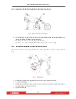
Page 20: ...han the tines The harrow is used for levelling the field surface after the tine section passage 3 5 3 Extreme Disc Adjustment in the Cross Harrow Type A We do this in order to reduce the depth of the trace at the edge of the machine s working width if any Fig 13 Extreme disc Extend the extension arm together with the coulter to the Operation position Loosen the bolts A Rotate the arm with the coul...

Page 21: ...the tine and tighten any loose connections before each use Measure the spring tension compression on a regular basis A sheared bolt A which breaks after exceeding a limit value is an additional safety measure USE ONLY GENUINE PROTECTION DEVICES Replace any working components as soon as the effects of the machine operation deteriorate Remove the screws D to replace the undercutters remove the screw...

Page 22: ... B and apply pressure on the cylinder A again causing it to slide to the stops B so that you can raise or lower the rear roller of the machine After initial setting of the roller actuators adjust the drawbar turnbuckle cylinder accordingly Make sure to set the working depth on the cylinders keeping in mind the parallel position of the frame during the machine operation Repeat these steps several t...

Page 23: ...that allow setting of 3 different lengths i e 2 2m factory setting 2 7m and 3 2m accordingly They are used for working with tractors with twin wheels mounted Perform this adjustment on the machine lowered Detach and remove the hydraulic hoses and electric cables from the front drawbar E Remove the nut and pull out the bolts D Pull the front part of the drawbar E to the next holes you can repeat th...

Page 24: ...he same time hold the coulter which can spontaneously fall down Move the coulter in the desired direction and align the holes in the coulter with the holes in the holder Secure the coulter with the bolt and the cotter pin The harrow may never operate below the level of operation of the tines The harrow is used to level the field area after the tine section pass 3 5 9 Adjustment of Scraping Disc Ha...

Page 25: ... in the harrow frame with the holes in the jibs Insert the securing bolts B 4 ea Lock the mechanisms with the bolts and the locknuts A The harrow may never operate below the level of operation of the tines The harrow is used to level the field area after the tine section pass 3 5 10 Adjustment of Extreme Disc Type B in the Cross DRIVE We do this in order to reduce the depth of the trace at the edg...

Page 26: ...ny work at it Also disconnect the machine from the tractor CAUTION THE HYDRAULIC SYSTEM IS PRESSURIZED CAUTION THE LIGHTING SYSTEM IS LIVE 5 2 Replacement of the Machine Components Replace all working parts wearing parts in due time to protect the other more expensive assemblies against wear Contact the manufacturer s service department in order to replace any component of the hydraulic system and...

Page 27: ... 4 5 5 2 M5 0 8 4 5 6 8 4 10 M6 1 8 11 15 17 M8 1 25 18 27 34 40 1 16 21 30 35 1 5 35 46 65 76 M10 1 25 31 41 57 67 1 27 36 50 59 M12 1 75 59 79 111 129 1 25 49 65 91 107 M14 2 92 124 174 203 1 5 76 104 143 167 M16 2 127 170 237 277 1 5 104 139 196 228 M18 2 194 258 363 422 1 5 135 180 254 296 M20 2 5 250 332 469 546 1 5 172 229 322 375 M22 2 5 307 415 584 682 1 5 212 282 397 463 M24 3 432 576 809...

Page 28: ... the lubrication points before lubricant injection Lubricate at the marked points If the machine worked less number of hectares please lubricate it before starting work and after its completion and at all lubrication points Fig 21 Lubrication points in CROSS Fig 22 Lubrication points in CROSS DRIVE ...

Page 29: ...ch axle pivots with kerosene and protect them against corrosion applying grease with brush repair spot defects of the paintwork by repainting when the machine is to be stored outdoors in winter disassembly the hydraulic cylinder together with the hoses and keep them in a dry well ventilated and possibly darkened room 5 8 Disassembly and Disposal After its working life the cultivator is to be scrap...

Page 30: ...OPERATING AND MAINTENANCE MANUAL CROSS S 28 COMMENTS AND NOTE ...

Page 31: ...OPERATING AND MAINTENANCE MANUAL CROSS S 29 COMMENTS AND NOTE ...

Page 32: ...OPERATING AND MAINTENANCE MANUAL CROSS S 30 COMMENTS AND NOTE ...

Page 33: ...ansport If so please specify what 3 When did you start work with the machine 4 How many ha have you worked with the machin 5 Tractor power HP 6 Which damages occurred 7 What is your general opinion about machine s work 8 What difficulties occur during the operation of the machine 9 Your comments regarding changes improvements of construction and machine operation 10 Your remarks concerning this ma...

Page 34: ...32 UNIA Sp z o o Szosa Toruńska 32 38 86 300 GRUDZIĄDZ tel 48 56 451 05 00 fax 48 56 451 05 01 Service tel 48 56 451 05 26 uniamachines com ...

Reviews: