UT3550 Battery Tester Users Manual
16
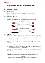
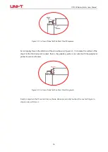
Figure 3-3-1-a Crown Probe Test Pen Short Circuit Diagram a
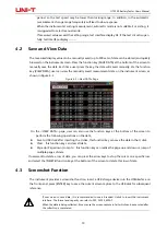
Second, apply force in the direction of the arrow shown in Figure 3-3-1-b to make the surface of the
object at the third red point contact, that is, the periphery probe is in contact with the peripheral
probe (Source and Source).
Figure 3-3-1-a Crown Probe Test Pen Short Circuit Diagram b
Finally, only when the three red dots as shown above are actually touched, the next setting zero
step can be performed
.


