Measurement Operation(12)
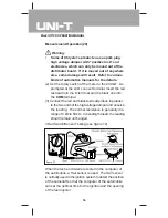
C.Solenoid or Relay Testing
1. The same as in Items 1 to 3 (Fuse Testing).
2. Connect the red and black test lead probes in parallel
to the two end of a solenoid or relay. The impedance
of most of solenoids or relay coils is less than 200
Ω
.
(See the details in the automotive manual.)
Warning:
l
Both ends of a general solenoid or relay are
connected with diodes.
l
Check to see if there is any damaged coil. Even
if the coil is found satisfactory, the solenoid or
relay may still be damaged. The relay may be
welded or worn due to the frequent sparking of
the contacts. The solenoid may be stuck when
the coil is in an on-position. Therefore some
potential problems cannot be found in testing.
D.Starting/Charging System Testing
The on-off package of the engine starting system consists
of a battery, engine starting button, solenoid and relay
starting buttons, lead connections and lines. During the
operation of the engine, the charging system keeps the
battery charged. This system consists of an AC generator,
voltage calibrator, lead connections and circuits. The
multimeter is an effective tool for the checking of these
systems.
1.Load-Free Battery Testing
Before testing the starting/charging system, test the
battery to see if it is fully charged.
(1) Set the rotary switch to 20 VDC.
Model UT105: OPERATING MANUAL
28
Summary of Contents for UT105
Page 7: ...Rules For Safe Operation 2 Model UT105 OPERATING MANUAL 7 ...
Page 8: ...Model UT105 OPERATING MANUAL 8 ...
Page 30: ......


