


• Press again. Hold day will be displayed on the LCD
and the clock will disappear
• Press day key to add override days. Press Program
key to reduce override days.
• Follow the Temporary / Designated Day Override
instructions above to change the Permanent
Manual Override temperature.
To End Override:
• Under Permanent Override press hold/return key
twice. Under a Designated Day Override press
the hold once. The thermostat will return to the
current program, and the HOLD display will be
canceled.
Filter Change Indicator
Your thermostat also keeps a record of the number
of hours your filter has been in use. To maximize your
system’s performance and energy efficiency, change or
clean your filter regularly.
• When the total system runtime for
heat and cool reaches 400 hours, FILT
will alternate with the current time on
the LCD display to remind you to clean
or change your system’s filter. FILT will
continue to flash until the counter is
set back to zero.
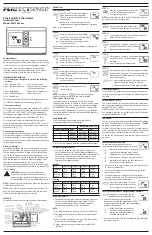
• Press to review total filter usage.
The display will blink FILT, then show
the filter monitor counter. After 15
seconds, the display will return to normal mode.
In this example, the counter is at 410 Hours,
26 Minutes.
• After changing or cleaning the system filter, press
and release the Filter Button. The usage hours
will display on the screen. Reset the display by
pressing and holding the Filter Button again until
the hours displayed are zero (0).
DIFF Setting
Your thermostat is set at the factory to cycle at 2°F (1°C)
above and below the set temperature (DIFF = 2). This
setting has been designed to provide a comfortable room
temperature under most conditions. However, if you find
your system cycling too often, the DIFF can be adjusted to
modify the cycle time.
• Press and hold BOTH up and down keys for three
seconds. The display will flash, and DIFF will be
displayed on the LCD.
• Press the up key to raise the DIFF to 3. This setting
INCREASES to cycle time by allowing your system
to run LONGER.
• Press the down key to lower the DIFF to 1. This
setting DECREASES the cycle time by causing your
system to run SHORTER.
The DIFF settings remain the same for both HEAT and
COOL. The DIFF can be changed at any time and is
independent of program times or temperatures. When
batteries are installed in the thermostat, the DIFF is reset
back to Setting 2.
Backlighting
Your thermostat has an electroluminescent lamp that
backlights the display for easy viewing in the dark. When
any key is pressed, the display is illuminated.
The display will remain illuminated for 8 seconds after the
last key is pressed. This allows the light to stay on if you
need to operate several keys.
Note: If the thermostat is in Low Battery warning
condition, the backlight will not operate. Replace with 2
new AA alkaline batteries to restore the backlight function.
Low Battery Warning
Your thermostat has a two-stage low battery
warning system. When the batteries are first
detected to be weak, the first stage low battery
warning is indicated by a battery symbol
flashing on the LCD display. At your earliest
convenience, you need to replace the batteries
with 2 new AA alkaline batteries.
When the batteries become too weak for
normal operation, the thermostat enters the second stage
low battery warning which shuts down the thermostat.
In this condition, BATT flashes alone on the display, and
the thermostat will turn your system off. Your system will
remain shut off until the batteries are replaced.
Note: The thermostat will still keep the current set
temperature and filter run time in memory until new
batteries are installed. After confirming that new batteries
have been inserted, the thermostat will return to normal
operation.
Auto Recovery
Auto Recovery calculates how early to turn
your system back on, so the room temperature
is comfortable by the start of the comfort
temperature program period. Auto Recovery
works in both heat and cool modes.
• When the thermostat is in Auto Recovery mode, the
display will alternate RECO with the time, and the
program indicator will flash.
• Auto Recovery can be disabled by sliding the Recovery
switch on the circuit board to disable.
• Auto Recovery will not operate if Permanent Hold or
Temporary Hold is in operation.
• Auto Recovery can be canceled manually if HOLD/
RETURN is pressed during the recovery process.
• Auto Recovery will be canceled and the thermostat will
change to next period.
Error Mode
If the thermostat is unable to control your
system due to a battery problem, the
thermostat will enter Error Mode. In this
condition, the thermostat flashes E1 or E2 on
the LCD display, and shuts off your system. To
correct this problem, replace the batteries with
2 new AA alkaline batteries, even if you have
recently replaced them. Remove the battery, hold any key,
then replace the battery again. You will need to reprogram
your thermostat and confirm normal operation.
If Error Mode returns, please contact us for further
information.
LCD Display Information LCD Display
Information
E1
Sensor error
E2
System switch error
Auto Cut Off
Your thermostat will automatically shut down in Heat
mode if the room temperature rises above 95°F (35°C).
It will shut down in Cool mode if the room temperature
drops below 45°F (7°C).
Note: If your system has malfunctioned and no longer
responds to thermostat controls, the Auto Cut-Off will have
no effect.
Mechanical Heat Backup
This thermostat includes a bimetal switch that will
automatically turn on the heat when the temperature
reaches about 41°F (5°C).
WARNING: This switch only activates the heating terminal
(W). The system itself must be capable of automatically
turning the fan on. Without normal fan operation, severe
damage to the heating system could result.
Selector Switches
In order for this thermostat to control your system, the
system type must be specified by the selector switches
on the printed circuit board inside the thermostat. There
is also a selector switch for your choice of Fahrenheit or
Celsius temperature display.
• F° / C° selector (Fahrenheit / Celsius)
Your thermostat is set for F° from the factory. In order to
change to C°, slide the switch to C°, remove the batteries,
wait for about 1 minute, then replace the batteries.
NOTE: You must press and hold any key about 2 seconds
when the batteries is out, then replace the battery or the
thermostat will not change temperature mode and all
programs and settings will be lost.
• Heating System Selector (HG – HE switch)
The factory position for this switch is in the HG position.
Leave it in this position if you have a gas furnace or an oil
burner. If you have an electric furnace, test to see whether
the heat and fan come on as expected after installation.
If the fan operation is normal, leave it in the HG position.
If the fan does not come on within a minute of the
thermostat calling for heat, change the switch position to
HE. The system selector has no effect in the cooling mode.
NOTE: HG position is for gas and most other systems. HE
position is for certain electric systems having a fan relay.
• System Selector (STANDARD – HEAT PUMP switch)
The factory position for this switch is in the STD position.
Leave it in this position if you have ANY system that uses
gas, oil, electric, or hot water heating. If you have a single
stage heat pump (no auxiliary or emergency heat source),
then slide the switch to the HP position. Be sure the
reversing valve wire is connected to the correct terminal
for your heat pump (Y/O) or (W/B).
• Auto Recovery Selector (DISABLE/ENABLE)
Your thermostat is set from the factory with the Auto
Recovery Feature enabled, which complies with the
EPA ENERGY STAR Program. If you prefer to use normal
recovery, slide the switch to the DISABLE position.
INSTALLATION
What You Need
This thermostat includes two #8 slotted screws and two
wall anchors for mounting. To install your thermostat, you
should have the following tools and materials.
• Slotted screwdriver(s)
• Small Philips screwdriver
• Hammer
• Electric drill and 3/16” bit
• Two 1.5V (AA) size alkaline batteries (included)
Remove Old Thermostat
CAUTION: Do not remove any wiring from existing
thermostat before reading the instructions carefully.
Wires must be labeled prior to removal.
IMPORTANT! Turn off the power to the furnace at the
main power panel or at the furnace.
Remove existing thermostat cover and thermostat. See
Figure 1. Some thermostats will have screws that must first
be removed. Once the wall mounting plate is exposed, look
for wires. If wires are not visible, they may be connected to
the back of the wall plate. Again, look for screws, tabs, etc.
Some models have doors that open to expose wires and
mounting screws. See Figure 1.
Typical Home Thermostats
Figure 1.
Wiring Labeling
• Each wire coming from the wall to the existing
thermostat is connected to a terminal point on that
thermostat. Each of these terminal points is usually
marked with a code letter as shown in Table A below.
• Note that this thermostat has multiple function terminals
that allow single stage heat pump capability. Standard
systems use: Rh, Rc, G, Y, W. Single stage heat pumps
use: R, Y, G, and O or B. Table A below shows the multiple
functions of the terminals. Use the terminals that match
your system.
• The number of wires in your system can be as few as two
(for heat only systems), as many as eight, or any number
in between. If you follow the labeling procedures
correctly, you do not have to be concerned about how
many wires there are.
• There is often no terminal marking
on the existing thermostat of
two wire, heat only systems. Just
connect either of the wires to the
RH terminal, then connect the
other wire to the W terminal to
complete the circuit.
• IMPORTANT! BEFORE DISCONNECTING ANY WIRES,
APPLY THE SELF-ADHESIVE LABELS PROVIDED TO THE
WIRE AS SHOWN IN TABLE A BELOW. For example,
attach the label marked W to the wire that goes to the W
or H terminal on your existing thermostat. IGNORE THE
COLOR OF THE WIRES since these do not always comply
with the standard.
• After labeling wires, disconnect them from the existing
thermostat.
• Remove existing wall plate. To make sure wires do not fall
back into wall opening, you may want to tape them to
the wall.
• If hole in wall is larger than necessary for wires, seal this
hole with insulating material so that no hot or cold air
can enter the back of the thermostat from the wall. This
air could cause a false thermostat reading.