

7
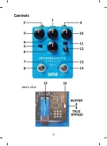
10. VOL:
This knob controls the output level of the pedal. Turning the
knob clockwise increases the output level.
11. BRT-FLAT SWITCH:
This switch is used to select the eq. mode of
the boost control. The
’BRT’
se ng produces a bright boost by
reducing the low frequencies in the signal. This mode is par cularly
useful when driving high gain amplifiers. The ’
FLAT’
se ng produces
a flat eq. boost.
12. BOOST:
This knob controls the amount of boost applied to the
output when the BOOST switch is on.
13. BOOST LED:
This LED indicates that the boost feature is turned
on.
14. BOOST SWITCH:
This switch turns the BOOST feature on and off.
Note: The boost feature only works when the pedal is on.
15. BATTERY:
The ba ery compartment is located inside the pedal
housing for connec ng a standard 9V DC ba ery (not included).
16. BUFFER-TRUE BYPASS SWITCH :
The OverUnity pedal design
allows for either buffered or true bypass of the input signal when the
pedal is off. This switch located inside the pedal housing allows you
to select which of these opera ng modes you prefer.


