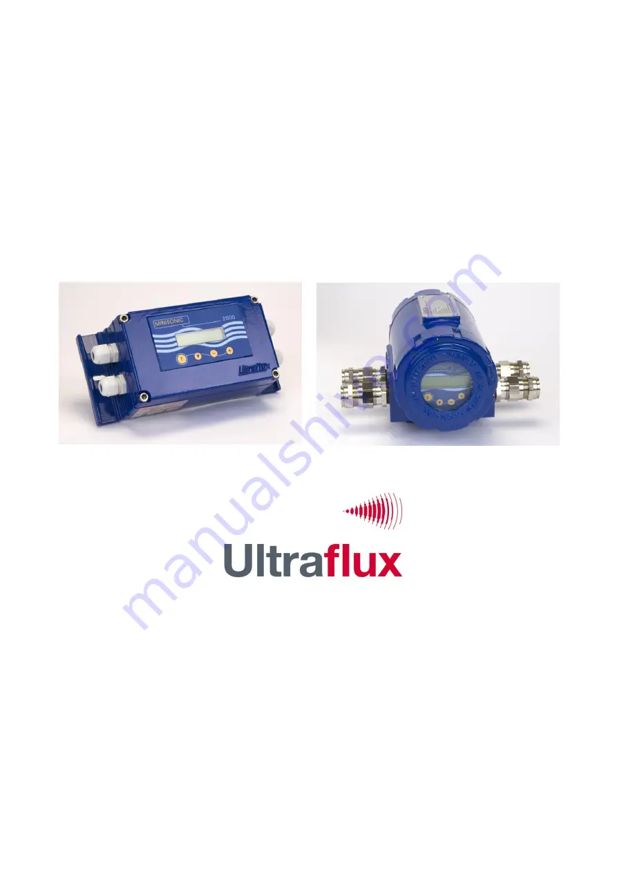
Ultraflux Minisonic 2000 User Manual Download Page 1

NT217 C GB1 


1 / 27 


User Manual 


Minisonic 600 

(Minisonic_600)


Minisonic 2000 

(Minisonic_2000)


Bâtiment TEXAS 

Éragny Parc 

9, Allée Rosa Luxemburg 
95610 ÉRAGNY, FRANCE 

Tél : 33 (0)1 30 27 27 30 

Fax : 33 (0)1 30 39 84 34 

www.ultraflux.net 


Ultraflux NT 217C GB1 

 
Edition : 29/04/2013 

Summary of Contents for Minisonic 2000

Page 1: ...inisonic 600 Minisonic_600 Minisonic 2000 Minisonic_2000 B timent TEXAS ragny Parc 9 All e Rosa Luxemburg 95610 RAGNY FRANCE T l 33 0 1 30 27 27 30 Fax 33 0 1 30 39 84 34 www ultraflux net Ultraflux N...

Page 2: ...al chord flow metering 600 B and 2000 B for dual pipe flow measurement configurations Speed 1 2 are devices for open channel flow velocity measurements This manual is specifically concerned with MiniS...

Page 3: ...nnections Wiring diagram 5 Converter assembling instructions Mechanical installation Electrical wiring 6 Probes installation 7 Setting and commissioning 8 Detailed Menu layout Measurement Display Menu...

Page 4: ...filled out by a supply of supports SU designed to assist with installation and rigorous repositioning for maintenance purposes When the material of the pipe concrete or the conditions corrosion viscos...

Page 5: ...ers diameter thickness of pipe L D allows the volume flow rate to be calculated whatever the developments of the product its temperature or its pressure Precision is even better when the Delta T measu...

Page 6: ...means of predicting the speed of sound to be compared with the result obtained by MiniSonic on the basis of the measured times and the dimensions as set up A deviation may require these values to be r...

Page 7: ...d of sound varies with the pressure and temperature and the coefficients rise in proportion to the reduction in the speed of sound For instance Influence of pressure 1 m s per bar for liquid butane an...

Page 8: ...ncerning high voltage human safety risks N A Only low voltage 60 V Concerning EMC EN 61000 EN 55022 et EN 50204 Concerning tightness IP EN 60529 Concerning ATEX Directive 94 4 CE EN 60079 0 General ru...

Page 9: ...erimposed assembly of several units Use flexible cables that are in conformity and secure the stuffing boxes used IP 67 Or F Function Choice menu or parameter Modification N B MiniSonic must be suppli...

Page 10: ...the probes To carry out the internal cabling of the probe cables on the MiniSonic card it is necessary to pull the support rack forwards remove the three front panel screws To comply better with EMC r...

Page 11: ...ONIC 600 2000 WIRING PLAN Low Voltage Supply If the GP 01 Module for 90 to 230 V AC Supply is installed see also NT 218 Internal cables must be kept as short as possible Cables are to enter through th...

Page 12: ...rs menu Analog outputs 4 20 mA BR 2 terminals 11 to 14 Flexible multipair cable These outputs are independent and galvanically isolated from each other but also from other MiniSonic circuits and by de...

Page 13: ...tation of the probes for the same pair parallel faces Important Once these adjustments finished it is necessary to measure with accuracy the distance L between transducers face to face and its project...

Page 14: ...of these above probes are delivered with a support which don t let other choice than to place them in Reflex mode This V mode must be preferred to all other mode as far you can place the transducers...

Page 15: ...Use same version than Firmware Refer to the manual supplied with the software CD ROM The fields of the main values to be entered are listed below under Heading 8 The software offers extended configura...

Page 16: ...ns mode and value And I Q quality indicator If I Q is less than 33 the last Measurement cycle is rejected Velocity of fluid and speed of sound N B This sound speed is a characteristic of the fluid at...

Page 17: ...to take place An operation will be requested allowing a provisional code to be calculated A second press on will provide access to the existing Languages choice field 8 3 Pipe Settings menu Access Pr...

Page 18: ...nt KH or data to do its calculation If MANUAL entry of coefficient depending on profile Laminar 1 333 or Turbulent 1 03 to 1 08 If AUTO entry of parameters Fluid viscosity Pipe roughness As well as th...

Page 19: ...L D Management of amplification gains ESC Mode recommended Echo Shape Control Otherwise If MANUAL Gain adjustment If AUTO Margin Over amplification compared to critical gain Go If SM choice position...

Page 20: ...ignment If copy of TOT 1 or TOT 2 Relay closing time F maxi If Threshold enter value for Q Reset to Zero of TOT 1 2 This function may be prohibited Parameter settings of two outputs 4 20 mA SA 1 SA 2...

Page 21: ...ngs menu normally reserved to Ultraflux It permits to adjust a coefficient which optimises the compensation with clamp on probes value 0 6 to1 8 Another parameter named Delta T Band permits to set a c...

Page 22: ...at the bottom end of the scale Cf Flow rate sub men Q rms Q max As long as they are accepted and therefore as long as rights are justified and authorized by a confidential code it is possible to work...

Page 23: ...itted meets your expectations Case 2 The measurement operates but may lack accuracy or is unstable Case 3 The measurement is not reliable or the MiniSonic is displaying a Fault Case 1 Although everyth...

Page 24: ...ameter Flow Rate Assembly Choice of probes is too low to claim any measurement accuracy Is it possible to revise these choices The measurement conditions reveal poor control of transitions from turbul...

Page 25: ...side PT 3 Emission Reception transit time PT 4 Echo Alternating signal peak to peak max 4 Volt 0 65 V negative threshold Echoes display investigations can also be done by using a DigiSonic E P portabl...

Page 26: ...NT217 C GB1 26 27 11 APPENDIX 1 Calibration file example of a MiniSonic with clamp on probes SE...

Page 27: ...NT217 C GB1 27 27 2 Calibration file example of a MiniSonic with SM insertion transducers...

Reviews: