Ultra Start KEU-300 Series Install Manual Download Page 4

12 Pin Connector....Continued

Purple- 

Positive Door Pin Input.

Connect this wire to vehicles that have a door pin that switches to 12 volts 
when the door is opened.

Green-

 Negative Door Pin Input.

Connect this wire to vehicles that have a door pin that switches to Negative 
when the door is opened.

Blue- 

Negative Hood/ Trunk Input.

Connect this wire to the hood and or trunk pin from the vehicle. Diode isolate 
if both the hood and trunk are being connected.

Brown Wires-

 Input/Output for Siren/ Horn. 

See Switch #3 for output type.

Positive Output

 - Connect one of the brown wires to 12 volts the other 

brown wire will then supply a 12 volt output. 

Negative Output-

  Connect one of the brown wires to Ground the other 

brown wire will than supply a Ground output. 
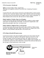
3 Pin Connector- 

Connect this harness before connecting the main 

harness. The system will automatically learn both positive and negative door 
locking systems. The default setting is negative door lock system.

To Learn the Door Locking System
1) 

Connect the three pin connector then the main power connector.

2) 

Wait three seconds for the programming to be completed, do not press 

any buttons until the 3 seconds have passed.

Green-

 Door Lock Input (Arm Pulse)

Connect this wire to the lock wire of the lock relay circuit.

Blue-

 Door Unlock Input (Disarm Pulse)

Connect this wire to the unlock wire of the unlock relay circuit.

Note: 

On systems with Driver’s Door Priority, connect this wire to the driver’s 

door unlock wire.

                                                                              Continued on next page...

INSTALL MANUAL   

                                                    REMOTE VEHICLE SECURITY

      PAGE 4

Summary of Contents for KEU-300 Series

Page 1: ...nterference received including interference that may cause undesired operation CAUTION Changes or modifications not expressly approved by the part responsible for compliance void the user s authority...

Page 2: ...onstant Input Horn Siren Input Horn Siren Output Flashing Park Light Output Second Channel Output Domelight Lock Output Positive Door Input Negative Door Input Hood Trunk Sensor Input Door Lock Wire I...

Page 3: ...n the transmitter is pressed twice within 3 seconds If the ignition turns on within 5 seconds the Shock Sensor will be automatically disabled until 10 seconds after the ignition shut back off Orange 5...

Page 4: ...of the brown wires to Ground the other brown wire will than supply a Ground output 3 Pin Connector Connect this harness before connecting the main harness The system will automatically learn both posi...

Page 5: ...olation Negative Door Lock System Cut the unlock wire and connect the switch side to both the Yellow sense wire and the striped side of the diode Connect the non striped side of the diode to the trans...

Page 6: ...off will deactivate the Siren Horn Output Switch 3 ON Horn Output OFF Siren Output In Horn Output Mode the output on the Brown wire will pulsed In Siren Output Mode the output on the Brown wire will...

Page 7: ...confirm reset Setting 1 Secure Valet Mode Turn the ignition key ON OFF ON OFF ON press and release the program switch The LED will flash One time to confirm setting one Hold the program switch until t...

Page 8: ...ode enabled 2 Chirps Default Car Jack Mode Disabled Setting 5 Shock Sensor Delete Turn the ignition key ON OFF ON OFF ON press and release the program switch 5 times The LED will flash Five times to c...

Reviews: