background image

Page 7

REMOTE VEHICLE STARTER

INSTALLATION MANUAL

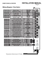
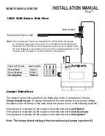
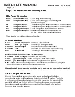
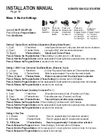
1500/ 1600 Series- Side View

Jumper Selections

1 2

3

The jumpers control the output from the White wire on the 6- pin harness. This is a

30amp relayed output

. To change the output of the wire access the jumpers by sliding

the plastic cover off the top of the case. Move the jumper to one of the following positions.

If the jumper is in position #1 the output on the white wire will be

2nd Starter

If the jumper is in position #2 the output on the white wire will be

2nd Accessory

If the jumper is in position #3 the output on the white wire will be

2nd Ignition*

Note: *The factory default setting of the selectable output jumper is position #3.

Output on White wire

Jumper position

Second Starter

Position 1

Second Accessory

Position 2

Second Ignition

Position 3

Jumpers

Not Available

Temperature Sensor Input

Note

: If the Temperature Sensor is installed the Cold Start Mode will operate

by monitoring temperate. If the sensor is not installed the Cold Start Mode
will function as Timer Mode. The temperature sensor can be installed under
the hood strapped to the radiator hose to monitor coolant temperature or left
mounted under the dash to monitor ambient air temperature.

Summary of Contents for 15 SERIES

Page 1: ...ponsibility of the vehicle owner to ensure that this is done The manufacturer accepts no liability or responsibility for accidental starting of the vehicle CARBON MONOXIDE Never Start in an Enclosed B...

Page 2: ...Module Manual Transmission Vehicles Page 11 Additional Connections Clutch Bypass Important Tach Notes Page 12 13 Auto Tach Learn Quick Learn Program Overview and Quick View Programming Page 14 15 Pro...

Page 3: ...ding style test light to test for wires in the vehicle Use only a Circuit Safe test light or digital Volt Ohm Meter It is the sole responsibility of the installer to test and verify all connections No...

Page 4: ...rts such as brake clutch and gas pedal linkages Do not place the module directly in front of a heater vent Installing the External Long Range Antenna To insure the best possible reception place the an...

Page 5: ...RED WHITE BLUE Yellow Orange Brown Red White White Violet Green Green White Purple Black Pink Blue White Blue White Black White Factory Re arm Output Starter Kill Anti Grind Output Factory Dis arm Out...

Page 6: ...GREEN RED RED WHITE BLUE Yellow Orange Brown Red White White Violet Green Green White Purple Black Pink Blue White Blue White Black White Factory Re arm Output Starter Kill Anti Grind Output Factory...

Page 7: ...be 2nd Accessory If the jumper is in position 3 the output on the white wire will be 2nd Ignition Note The factory default setting of the selectable output jumper is position 3 Output on White wire Ju...

Page 8: ...for factory alarm re arm Programmable output See Menu 3 2 Orange St kill and Negative output when locked and during remote start Anti Grind Used for optional starter disable and anti grind relay Prog...

Page 9: ...and place the antenna in the center of the windshield behind the rear view mirror Run the cable behind the head liner and A pillar panels to the module under the dash The Antenna Must Be Connected Bef...

Page 10: ...A C Tach Source Above 2volts AC Pink Brake Switch Connect To When Brakes Is Applied Manual Transmission Connections M Models Only Black Wht Park Brake Input Connect to Park Brake wire Green Door Pin I...

Page 11: ...ring remote Starting This is a temporary bypass the clutch switch should never be disconnected or altered to not work as it is indented to As a Safety Switch The clutch switch is usually a 2 wire swit...

Page 12: ...lights do not flash in auto tach learn mode it may be necessary to connect to a different tach source It is important the ignition output from the remote starter is connected to a wire that does not...

Page 13: ...rmal idle RPM Vehicles such as Toyota and Honda will run at a very high idle for a number of minutes when first started If tach learned when the vehicle is at high Idle then remote started when the ve...

Page 14: ...2 3 flashes honks Setting 3 c Turning the ignition key to the Off position or 30 seconds of no activity will exit Program Mode This will be confirmed with a light flash and a long horn optional honk...

Page 15: ...Time 4 Min 45 Min 15 Min 5 Crank Time 10 second 3 seconds 5 seconds 6 Starter Disable GWR Active Passive GWR 7 Safety Start Mode Press twice Press once Menu 4 Press 1 Flash 1 Low Idle Learn Low Idle...

Page 16: ...75 Second Lock Unlock Pulses Press Release the Program Button 3 Times Setting 3 Confirmed with 3 LED flashes Press Hold the Program Button until the appropriate of park lights horn optional honks then...

Page 17: ...onks Normal Medium Horn Output Pulses Press Release the Program Button 3 Times Setting 3 confirmed 3 LED flashes Press Hold the Program Button until the appropriate of park light horn optional honks t...

Page 18: ...o proceed to the next step Setting 3 Rearm Output Auxiliary Connector Pin 1 1 Type 1 1 Flash Honk Pulse after start and with lock Provides Lock Pulse 2 Type 2 2 Flashes Honks Pulse after start only Pr...

Page 19: ...ssive 2 Flashes Honks when locked 30 seconds after ignition is Off or unlock is pressed 3 Anti grind 3 Flashes Honks Output during remote start only Anti grind Bypass module Press Release the Program...

Page 20: ...flash and the horn will honk one time Each time the park lights flash and the horn honks the setting is reduced 5 Release the Program Button Exit Program Mode and test remote starter Setting 3 Under...

Page 21: ...ansmitters to be used must be programmed at the same time All transmitters not programmed at this time will be erased from memory for security The system holds a maximum of 4 transmitter codes includi...

Page 22: ...e Door Locks More Than 250ma Positive Type Door Locks Note When installing relays always use a fused power source Blue Green Lock Un lock Vehicle Lock Unlock Switch To Control Relay or Actuators 87 86...

Page 23: ...7a 30 Ground DIAGNOSTICS 13 87 86 85 87a 30 87 86 85 87a 30 Blue Green Lock Un lock To Vacuum Pump Fused 12V x Cut Ground Page 23 REMOTE VEHICLE STARTER INSTALLATION MANUAL 5 Wire Reverse Polarity Typ...

Page 24: ...t attempts without starting Being that the installer does not always see when the system shuts down or fails to start Diagnostic Memory will store in memory up to four shutdown codes This information...

Reviews: