System Interconnects
Chapter 3: Installation
Page 3-20
VersaMux-4000 Operation & Installation Guide
Part No. 24001157
Revision C
System Interconnects
All I/O connections are made through the back of the VersaMux-4000. Pin-outs
and connector identifications are provided in
.
NOTE:
Copper communications cables that attach to DNE products should be shielded
and the drain wire tied to the metal shell of the connector body (if applicable). If
required, place a split-core Fair-Rite, part number 0444167281 or equivalent, on
the NRZ cable, close to the EUT to be compliant with FCC Part 15, Subpart B, Class
A, 2004.
NRZ
The NRZ interface of the VersaMux-4000 accepts and generates RS-422 (Balanced)
signals using an EIA-530 DB-25 connector (the pin numbers are EIA-530, DCE).
provides a pin diagrams for the DCE NRZ connector with EIA-530
signal nomenclature.
provides a pin diagrams for the DTE NRZ
connector with EIA-530 signal nomenclature.
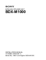
Figure 3-18
NRZ Input/Output Connector with EIA-530 Signal Nomenclature (DCE)
DCE Mode
Shield
Transmitted Data (A) +
Transmitted Data (B) -
Transmit Signal Element Timing DCE Source (B) -
Transmit Signal Element Timing DTE Source (A) +
Transmit Signal Element Timing DTE Source (B) -
Receiver Signal Element Timing DCE Source (A) +
Receiver Signal Element Timing DCE Source (B) -
Transmit Signal Element Timing DCE Source (A) +
Pin 1
Pin 2
Pin 3
Pin 7
Pin 9
Received Line Signal Detector (A) +
Received Line Signal Detector (B) -
Pin 8
Pin 10
Pin 11
Pin 12
Pin 13
Pin 14
Pin 15
Pin 16
Pin 17
Pin 19
Pin 24
Pin 23
Received Data (A) +
Received Data (B)-
Signal Common
Signal Common
Pin 4
Pin 5
Pin 6
Pin 20
NRZ EIA-530A (DCE)
Clear To Send -
Request To Send (A) +
Clear To Send (A) +
DCE Ready
Request To Send (RTS) -
DTE Ready