


UHP-200 HIGH-THROUGHPUT SATELLITE ROUTER
GENERAL DESCRIPTION AND INSTALLATION GUIDE, v3.2
© UHP NETWORKS INC 2015
12
www.uhp.net
2.
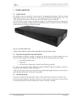
OPERATIONS
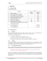
2.1
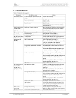
Operational limits
Table 1 Operational limits
#
Parameter
Limits
Minimum
Maximum
1
PSU Input voltage
100 VAC
240 VAC
2
Output current at Tx Out interface
-
2 A
3
Input voltage on the Tx Out interface
-
24 V
4
Output current at Rх SCPC or RX TDMA
-
0,75 А
5
Input voltage on other interfaces
18 V
6
Operational temperature
0
С
+40
0
C
7
Relative humidity (@ 25
0
С)
0%
90%
8
Atmospheric pressure (mm Hg)
720
770
9
Mechanical impacts (acceleration with an amplitude
not exceeding 1,25 mm):
- in a range 0,5 – 15 Hz:
- in a range 15-40 Hz:
- in a range 40-300 Hz:
2,45 m/s
5,88 m/s
14,7 m/s
2.2
Preparation for use
2.2.1
Unpacking
Before opening the packaging please check a safety of transport container. If there is any visible damage of
packaging you should keep it as long as the delivered equipment will be properly tested.
Unpack the router in the following order:
1.
Extract from a cardboard box the router and the power cord.
2.
Store all packing materials for further storage or shipment of equipment.
3.
Check equipment for the presence of any possible damage resulting from transportation.
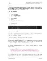
2.2.2
Installation
UHP-200 Router is designed for installation into a standard 19 inch telecommunication rack. Movable rack mounts
allow installing the router its indicators’ or interfaces’ panel facing forward. When installing the router in a rack or
on a flat surface, make sure you have enough free space for ventilation of the router.
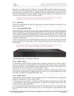
2.2.3
Connecting to external devices
All wire connections must be performed before powering up the router. IF cable connectors should be screwed to
the router without use of any mechanical instruments. Please, avoid excessive force when connecting IF cables.
WARNING!
D
O NOT CONNECT OR DISCONNECT ANY CONNECTING CABLES TO THE ROUTER WITH THE POWER ON
.
T
HIS
CAN LEAD TO A FAILURE OF THE ROUTER AND CONNECTED DEVICES
.
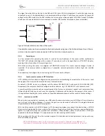
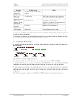
Typically, the router UHP-200 is connected to individual RF frequency equipment (ODU). In such configuration the
TX output of the modulator is connected to the BUC. The router will supply the BUC with 24V power and 10MHz
reference signal. If the router is connected to the BUC via splitter/combiner it should pass respective DC and
reference signals.


