background image

13

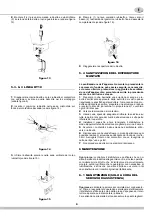
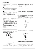
handle (see figure 6).

figure 6

1

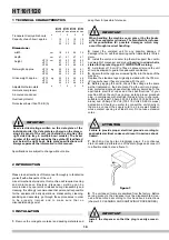
Take the bowl away from the machine and turn it upside

down. Remove the faucet body from the bowl (see figure 7).

figure 7

5. 3. 2. 2  HT10 LINE

1

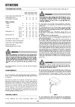
Remove the faucet top cover.

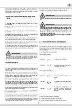
Push (1) the dispensing handle and remove the pinch tube from

its vertical seat (2) in the faucet body and from its horizontal

one (3) from the bowl bottom (see figure 8).

figure 8

2

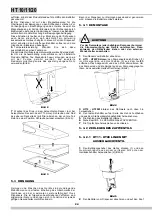
Take the bowl away from the machine and turn it upside

down.

Pull (1) the tab release lever and at the same time, turn to the

left (counterclockwise) the faucet body till it gets free, together

with faucet cover, from the bowl (see figure 5).

5. 3. 3  CLEANING

1

Prepare at least two gallons of a mild cleaning solution of

warm (45-60 °C 120-140 °F) potable water and dishwashing

detergent. Do not use abrasive detergent.

Important: if present, follow label directions, as too strong a

solution can cause parts damage, while too mild a solution will
not provide adequate cleaning.

2

Using a brush, suitable for the purpose, thoroughly clean all

disassembled parts in the cleaning solution.

3

Do not immerse the lighted top covers in liquid. Wash them

apart with the cleaning solution. Carefully clean their undersi-

des. 

4

In the same manner clean the evaporator cylinder(s) using

a soft bristle brush.

5

Rinse all cleaned parts with cool clean water.

5. 3. 4  SANITIZING

Sanitizing should be performed immediately prior to

starting the machine. Do not allow the unit to sit for

extended periods of time after sanitization.

1

Wash hands with a suitable antibacterial soap.

2

Prepare at least two gallons of a warm (45-60 °C 120-

140 °F) sanitizing solution (100 PPM available chlorine concen-

tration or 1 spoon of sodium hypoclorite diluted with two litres of

water) according to your local Health Codes and manufactu-

rer’s specifications.

3

Place the parts in the sanitizing solution for five minutes.

4

Do not immerse the lighted top covers in liquid. Carefully

wash their undersides with the sanitizing solution.

5

Place the sanitized parts on a clean dry surface to air dry.

6

Wipe clean all exterior surfaces of the unit. Do not use abra-

sive cleaner.

IMPORTANT

Do not attempt to wash any machine components in a

dishwasher.

ATTENTION

Before any disassembly and/or cleaning procedure make

sure that the dispenser is disconnected from its power

source.

IMPORTANT

In order to prevent any damages to the dispenser use

only a detergent suitable with plastic parts.

ATTENTION

When cleaning the machine, do not allow excessive

amounts of water around the electrically operated com-

ponents of the unit. Electrical shock or damage to the

machine may result.

Summary of Contents for HT10/1

Page 1: ...MANUALE D ISTRUZIONI OPERATOR S MANUAL CARNET D INSTRUCTIONS GEBRAUCHSANWEISUNG MANUAL DE INSTRUCCIONES HT 10 11 20...

Page 2: ...Milano ITALY declararamos bajo nuestra responsabilidad que los productos HT 10 1 2 3 4 HT 11 1 2 3 4 HT 20 1 2 3 4 responden con las siguientes Normativas En cumplimiento de las Normas EC 73 23 EC 98...

Page 3: ...l intervento a domicilio l ac quirente tenuto a corrispondere il diritto fisso di chiamata in vigore presso il fabbricante alla data dell intervento Qualora l apparecchio venga riparato presso uno de...

Page 4: ...o contatti di terra ed adatta a cor renti di almeno 10 A 250 V per aree aventi tensioni di 220 230 V 50 60 Hz e 20 A 250 V per aree aventi tensioni di 100 115 V 50 60 Hz Nel caso si volesse realizzar...

Page 5: ...CRIZIONE DEI COMANDI Il distributore provvisto di un interruttore generale e per ogni contenitore di un interruttore per il comando del relativo dispo sitivo di agitazione pompa nelle Linee HT11 HT20P...

Page 6: ...erate di carattere generale e possono variare per effetto della regolamentazione sanitaria vigente Prima dello smontaggio per il lavaggio il distributore deve esse re svuotato del prodotto 5 3 1 SMONT...

Page 7: ...tare il contenitore dall apparecchio e capovolgerlo Sganciare 1 la leva smontaggio rubinetto e contemporanea mente ruotare 2 verso sinistra senso antiorario tutto il corpo rubinetto fino a sganciarlo...

Page 8: ...re capitolo 5 3 6 RIMONTAGGIO RUBINETTO 3 Rimontare la guarnizione di tenuta del contenitore nella sua sede in modo che la corona di maggiore spessore risulti esterna al contenitore stesso vedere figu...

Page 9: ...o varechina in proporzione di 1 cucchiaio ogni 2 litri di acqua 2 Versare la soluzione nei contenitori 3 Usando una spazzola adeguata strofinare la soluzione su tutte le parti al di sopra del livello...

Page 10: ...100 115 Volts 50 60 Hz areas applications Should you prefer to connect the unit directly to the mains connect the supply cord to a 2 pole wall breaker whose contact opening is at least 3 mm Do not us...

Page 11: ...Their functions are as follows Power switch Mixing device switch To operate the dispenser 1 Set power switch to I position 2 Set mixing device switch es to I position 5 2 OPERATION HELPFUL HINTS 1 Th...

Page 12: ...ed tube Take impeller and bearing pin away from pump housing by removing the retaining pin figure 3 3 HT10 HT 20 Mlines remove stirrer by lifting up 4 Remove the empty bowl by lifting its faucet side...

Page 13: ...clean the evaporator cylinder s using a soft bristle brush 5 Rinse all cleaned parts with cool clean water 5 3 4 SANITIZING Sanitizing should be performed immediately prior to starting the machine Do...

Page 14: ...cover and the faucet body by reversing disas sembly operations see figure 5 2 Push 1 the dispensing handle and insert 2 the pinch tube into its vertical seat in the bowl bottom see figure 10 figure 1...

Page 15: ...nd on the underside of the top cover s 4 Install the top cover s and operate the unit Allow the solu tion to agitate for about two minutes Drain the solution out of the bowl s 5 Use fresh product to c...

Page 16: ...pour les secteurs ayant des tensions de 220V 230V 50 60 Hz et 20 A 250 V pour les secteurs ayant des tensions de 100 115 V 50 60 Hz Pour r a liser un branchement fixe au r seau brancher le c ble un i...

Page 17: ...Monter les couvercles sur les r servoirs en s assurant que ceux ci sont positionn s correctement 5 Agir sur les interrupteurs voir chapitre 5 1 DESCRIPTION DES COMMANDES 6 Le distributeur doit toujour...

Page 18: ...changer l orien tation du couvercle d visser la partie sup rieure du couvercle qui contient la photo et la tourner de 180 La partie inf rieure doit rester la m me place Remettre les vis vedere figure...

Page 19: ...ver le r servoir de l appareil et le retourner Tirer 1 le levier de d crochement du robinet et en m me temps tourner 2 vers gauche le corps du robinet jusqu le d crocher du r servoir avec le couvercle...

Page 20: ...ir sa place 2 Voir chapitre 5 3 6 REMONTAGE DU ROBINET 3 Replacer le joint du r servoir en laissant la couronne plus paisse au dehors du r servoir voir figure 10 figure 10 4 Placer le r servoir sur l...

Page 21: ...une proportion d une cuill re tous les 2 litres d eau 2 Verser la solution dans les r servoirs 3 A l aide d une brosse ad quate frotter la solution sur toutes les parties au dessus du niveau de la so...

Page 22: ...230 V 50 60 Hz und 20 A 250 V f r Gebiete mit Spannungen von 100 115 V 50 60 Hz Soll das Ger t direkt an das Stromnetz angeschlossen werden das Kabel mit einem zweipoligen Wandschalter verbinden desse...

Page 23: ...regat schaltet automatisch ab sobald das Produkt abgabefertig ist Die R hrwerke bleiben in Betrieb 8 Zur guten Konservierung des Produkts mu der Dispenser auch in der Nacht funktionieren 5 1 BESCHREIB...

Page 24: ...NIGUNG Reinigen und Waschen des Ger ts sind grundlegende Ma nahmen zur perfekten Erhaltung des Geschmacks der Getr nke und der maximalen Leistunsf higkeit Ihres Dispensers Die im folgenden beschrieben...

Page 25: ...h lter drehen 2 Bild 6 5 3 3 WASCHEN 1 Eine Sch ssel mit ungef hr acht Liter hei em Wasser 45 60 C f llen und unter Beachtung der Vorschriften des Herstellers spezielles Reinigungsmittel hinzuf gen ei...

Page 26: ...in den Beh lter einsetzen dabei bleibt der dickere Teil der Dichtung au erhalb des Beh lters Bild 10 Bild 10 4 Beh lter auf des Ger t aufsetzen so da die Dichtung berall an dem Verdampfer anliegt und...

Page 27: ...eh lter sch tten 3 Mit einer geeigneten B rste die L sung auf allen Teilen die aus der L sung herausragen und auf der Unterseite des Deckels verreiben 4 Den Deckel aufsetzen und den Dispenser laufen l...

Page 28: ...as con tensiones de 220V 230V 50Hz 60Hz y 20 A y tensi n de 250V para reas con tensiones de 110V 115V 50 60Hz En el supuesto de realizar una conexi n fija a la red conectar el cable a un interruptor d...

Page 29: ...el producto el distribuidor deber funcionar tambi n durante la noche 5 1 DESCRIPCION DE LOS MANDOS El distribuidor est provisto de un interruptor general y para cada contenedor de un interruptor para...

Page 30: ...la reglamentaci n de higiene vigente Antes del desarmado para el lavado del distribuidor debe quitarse todo el producto 5 3 1 DESMONTAJE 1 Quitar la tapa del contenedor 2 Series HT11 HT20PS quitar el...

Page 31: ...a sentido antihorario todo el cuerpo del grifo hasta desengancharlo completamente junto al cubre grifo ver figura 6 5 3 3 LAVADO 1 Poner en una palangana aproximadamente ocho litros de agua caliente 4...

Page 32: ...e modo que el borde de mayor espesor se quede exteriormente al mismo contenedor ver figura 10 figura 10 4 Colocar el contenedor encima del distribuidor con la junta en correspondencia del evaporador y...

Page 33: ...ito de sodio lej a uso alimenticio en la proporci n de 1 cucharadita por cada 2 litros de agua 2 Verter la soluci n en los contenedores 3 Usando un cepillo apropiado fregar con la soluci n todas las p...

Page 34: ...bowl Tube p pompe r servoir 11It Spr delrohr f Beh 11 It Tubo de flujo conten 11 It 2 22800 01200 Tubo a L L shaped tube Tube L L F rmigerohr Tubo a L 3 22800 03100 Molla ritegno albero pompa Pump im...

Page 35: ...T 20 3 HT 20 4 Aspas BS14 HT 20 2 HT 20 3 HT 20 4 31 33800 00803 Magnete motore Motor magnet assembly Aimant du moteur Motorrahd Embrague magnetico 32 22800 04800 Staffa supporto motore Pump motor bra...

Page 36: ...36 HT 10 A AL ELENCO RICAMBI SPARE PARTS LIST LISTE DES PIECES DE RECHANGE ERSATZTEILLISTE DESCRIPCION PIEZAS DE REPUESTO...

Page 37: ...izione di tenuta Bowl gasket Joint du r servoir Beh lterdichtung Junta contenedor 31 27109 00000 OR per albero centrale Central shaft OR Joint OR pour arbre central 0 Ring f r Zentralwelle OR para eje...

Page 38: ...mp mixer Pompe brasseur Pumpe R hrwerk Bomba agitador 14 Ventilatore Fan Motor Moteur ventilateur L ftermotor Ventilador 15 Compressore Compressor Compresseur Kompressor Motocompresor 16 Interr mescol...

Page 39: ...39 NOTE NOTES NOTES ANMERKUNGEN NOTAS...

Page 40: ...Ugolini spa Via dei Pioppi 33 20090 Opera MI Tel 02 530059 1 Fax 02 530059260 www ugolinispa com E Mail sales ugolinispa com 2400_99 V3 2 11L21...

Reviews: