


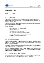


Page 2
37360 Instruction Manual (Rev. 0)
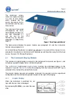
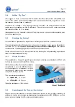
The instrument compo-
nents are neatly arranged
in a box of new design,
which contains the I.R.
source, the sensor, the mi-
crocontroller and the elec-
tronic circuit.
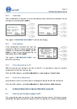
The instrument front panel
encompasses the Com-
mand-Display Module (2),
see also paragraph 2.1
and the slot for the
memory key (3), see also
paragraph 3.1-Data Porta-
bility3.1.
Figure 1 “Front Panel and USB slot”
The back panel embodies the power module, see paragraph 4.5, and the connection
module, see paragraph 4.6.
An inclined Mouse Restrainer is supplied as optional, to be used with the mouse to com-
pensate for its tendency to hold its tail at 45 degrees up and therefore away from the heat
source. See also 5.5.1Mouse Restrainer.
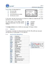
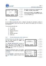
2.1 The
Command-Display
Module
This module of original design is located on the instrument front panel, see figure 1, and
comprises a graphic display and a command keyboard.
The
multifunction
liquid-crystal
graphic-display
monitors the withdrawal latency to the
nearest 0.1 second;
latency time
is the time elapsing from the moment the START key is
activated to the moment the animal flicks its tail.
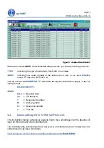
The graphic display presents all available command: the operator sets the experiment
configuration via the command keyboard located on the right of the display.
2.1.1 Graphic
Display
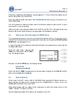
When the instrument is switched on, our
logo with the two mice is displayed.
By depressing
F4
(
ESC
), you enter the user
area.
3
2
1


