UfiSpace S9501-28SMT Hardware Installation Manual Download Page 21

S9501-28SMT


 Hardware Installation Guide  |   18

Connecting Power

9.1  DC Version

Figure 2

9

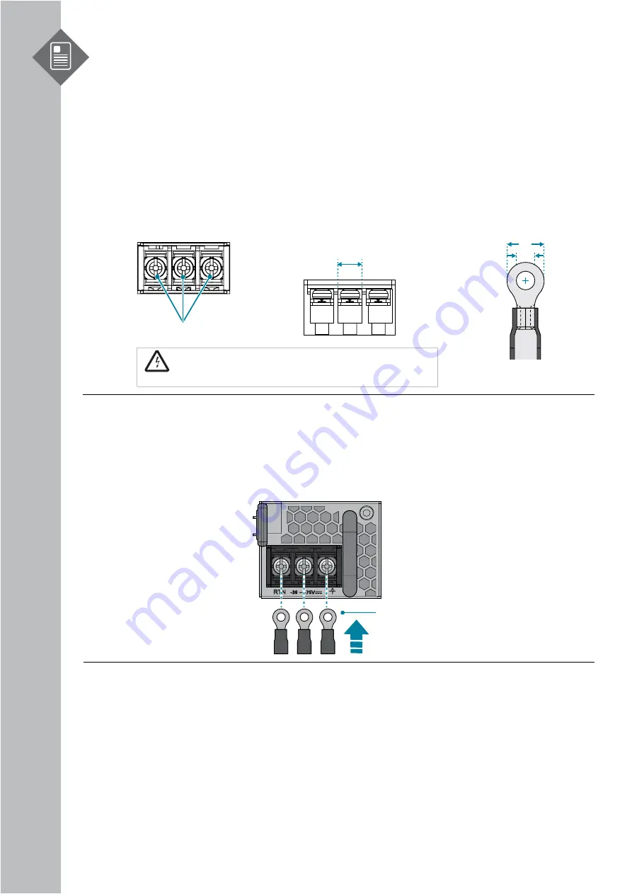
d2 > 3.5 mm, W < 8.2 mm

Screw Size: M3.5

8.2 mm

W

d2

Figure 2

8

.

War

n

ing!


Dangerous voltage! 

Must be powered off before removing!

Verify that all electrical connections are grounded before powering on

3. Tighten the screws to the specified torque.

Tighten the screws to a torque value of 6.94lbf.in (+/-10%). If the torque is not enough,

the lug will not be secure and may cause malfunctions. If the torque is too much, the

terminal block or lug may be damaged.

Green/


Y

ellow

 Ground Wire


(m

in

.


size 

1

6 AWG

)

1.

Ensure there is enough power to supply the system.

The maximum system power consumption is 

200

 watt. The minimum power distribution

unit fuse requirement is 15 ampere based on the lowest voltage of 42.6 volts

2.

Attach the power cable.

Locate the DC power screw-type terminal block on the DC PSU. Attach the UL 1015, 14

AWG DC power cable (not provided within the package contents) to the DC inlet

connector on the PSU.

4.

Feed DC power into the system.

The PSU will immediately output 12V and 5VSB to the system when a -48V DC power
source is applied. The PSU has a built in 20 amperes, fast acting fuse based on the PSU
maximum capacity, which will act as a second tier system protection in case the power
distribution unit’s fuse is not functioning.

5.

Verify that the power supply is operating.

If connected correctly, when turned on, the LED on the PSU will light up with a Green

color designating normal operation.

Summary of Contents for S9501-28SMT

Page 1: ...S9501 28SMT Disaggregated Cell Site Gateway Hardware Installation Guide R1 0...

Page 2: ...our System 7 4 1 S9501 28SMT DC Version Overview 7 4 2 S9501 28SMT AC Version Overview 8 4 3 DC Version PSU Overview 9 4 4 AC Version PSU Overview 10 4 5 Fan Overview 10 4 6 Port Overview 11 5 Rack Mo...

Page 3: ...e USB Extender Cable 23 12 2 Connecting a Cable to the ToD Interface 23 12 3 Connecting a Cable to the BITS Interface 23 12 4 Connecting the GNSS Interface 23 12 5 Connecting the 1PPS Interface 24 12...

Page 4: ...ted open network infrastructure to lower costs and rapidly scale existing services for edge computing mobile backhaul and broadband access applications The S9501 28SMT is future proofed with a powerfu...

Page 5: ...2 Insula on Wire Lead Ground Wire size 6 AWG 0 5 0 02 12 7 0 5 mm 14 AWG wire with ring terminal for DC power supply 6 AWG wire for grounding Wire stripping tools for stripping 6 AWG copper wire Conso...

Page 6: ...r 19 rack width 4 Post Racks 33 For 22 33 rack depth Space Clearance The S9501 28SMT chassis width is 17 32 inches 44cm and shipped with a rack mount brackets suitable for 19 inch 48 3cm wide racks Th...

Page 7: ...8V DC 8 4 ampere maximum or AC version 100 240V 3 1 5 ampere Installation spacing and weight load requirement S9501 28SMT is 1RU 1 75 4 5cm in height 19 48 3cm in width and 16 40 6cm in depth without...

Page 8: ...3 Rack Mount Bracket 1 98 x 1 69 x 0 79 19 width rack 50 4 x 43 x 20mm 2 pcs 0 15lbs 67 2g 2 pcs 0 07lbs 33 6g pcs 4 Screw Kit for Rack Mount Bracket 8 x Screws M4 0 L6 5mm 8 sets 0 01lbs 6 5g set 5 A...

Page 9: ...ound lug 0 022lbs 10g Rack mount bracket 0 07lbs 33 6g Adjustable mounting rail 0 89lbs 405g USB extension cord 0 021lbs 9 7g Screw kit for ground lug 0 008lbs 3 8g per set Screw kit for rack mount br...

Page 10: ...28SMT Hardware Installation Guide 7 4 Identifying Your System 4 1 S9501 28SMT DC Version Overview SPEC LABEL CUS BAR CODE SPEC LABEL CUS BAR CODE D 11 89 302 mm W 17 32 440 mm H 1 713 43 5 mm 1RU Fig...

Page 11: ...pe A USB 16 x 2 5G SFP 2x10G SFP MACsec TOD Console Grounding Lug Figure 6 4 2 S9501 28SMT AC Version Overview Figure 7 4 x 1G RJ45 SPEC LABEL CUS BAR CODE SPEC LABEL CUS BAR CODE D 11 89 302 mm W 17...

Page 12: ...placeable unit FRU Figure 9 AIR FLOW 50 5 2 6 0 25 Handle Color Black EMI Shielding Gaskets 3x SPEC LABEL CUS BAR CODE 39 85 40 2 198 5 Latch Color Blue Figure 10 3 x 4028 Fan Modules 1PPS 10MHz AC PS...

Page 13: ...re Installation Guide 10 4 4 AC Version PSU Overview 1 1 hot swappable power supply unit PSU field replaceable unit FRU Figure 11 Figure 12 4 5 Fan Overview 2 1 hot swappable fan field replaceable uni...

Page 14: ...iew Port ID Form Factor Maximum Support Distance Support Speed 0 3 RJ45 238 01ft 100m 1GE 100M 4 19 SFP 24 85mi 40km 2 5GE 1GE 100M 20 25 SFP 24 85mi 40km 10GE 2 5GE 1GE 26 27 SFP 24 85mi 40km 10GE 2...

Page 15: ...ent in position on the rack while the other secures it in place 1 Secure the rack mount brackets onto the router Align the rack mount brackets with the holes provided on the both sides of the case and...

Page 16: ...into the fan bay and gently push until it is flush with the case 5 Secure the captive screw on the fan module to lock the fan in place The fan modules are hot swappable field replaceable units FRUs wh...

Page 17: ...g as the remaining second PSU is installed and in operation The PSUs comes pre installed and the following are instructions on how to install a new PSU DC AC Caution Shock hazard For safety please dis...

Page 18: ...bay ensuring the PSU s power connector is in the correct position 4 Carefully slide the new PSU into the power bay and gently push until it is flush with the case 5 An audible click will be heard when...

Page 19: ...ion from a size 6 AWG grounding wire not provided within the package contents leaving 0 5 0 02 12 7mm 0 5mm of exposed grounding wire 3 Insert the exposed grounding wire all the way into the hole of t...

Page 20: ...1 Star Washers 4 pcs Loca on 2 Ground Screw 2 pcs Figure 27 5 Locate the designated location for securing the grounding lug which is located on the side of the router 6 Using 2 M4 screws and 4 washers...

Page 21: ...em power consumption is 200 watt The minimum power distribution unit fuse requirement is 15 ampere based on the lowest voltage of 42 6 volts 2 Attach the power cable Locate the DC power screw type ter...

Page 22: ...system power consumption is 200 watts with an input voltage of 100 240V and 3 amperes 2 Attach the power cable Plug the power cord into the AC PSU and secure it tightly 3 Verify that the power supply...

Page 23: ...System power fail FAN OFF No fan modules present Solid Green All fan modules work well Blinking Green Reserved Solid Amber Reserved Blinking Amber One or more FAN module s fail STAT OFF System x86 BMC...

Page 24: ...in learning state Self survey is not completed NOTE Need NOS to activate this feature Blinking Amber GNSS antenna is short to ground NOTE Need NOS to activate this feature 10 2 PSU FRU LED LED Condit...

Page 25: ...lug a RJ45 serial cable into the console port and connect the other end to the computer Cable types may vary depending on the model 2 Check for serial control availability Disable any serial communica...

Page 26: ...front panel of the router 2 Connect the other end of the cable to the BITS patch or demarcation panel 3 Below is the pinout for the BITS port BITS_T1_RTIP_CONN BR1 1RX 1RX 1TX B4 B5 1TX B7 B8 BR2 BR3...

Page 27: ...nize the cables For easier management label each fiber optic cable and record its respective connection Maintain a clear line of sight to the port LEDs by routing the cables away from the LEDs Caution...

Page 28: ...ment damage may result Caution Use of controls or adjustments or performance of procedures other than those specified herein may result in hazardous radiation exposure Warning Do not use optical instr...

Page 29: ...www ufispace com...

Reviews: