OPERATING INSTRUCTIONS
Auto Power Off
After powering off, the meter will turn on again when you change ranges,
rotate the selector dial or press a button.
NOTE:
The APO is disabled during MIN/MAX mode.
Backlight/Worklight (DL379B and DL389 only)
Press and hold the HOLD button for 2 seconds to activate. Lights
automatically turn off in 2 minutes to save battery life.
NOTE:
After activating the lights, quick press to activate the hold mode.
Automatic / Manual Range
The meter defaults to auto range mode and AT is indicated on the display
while active. Press the RANGE button to cycle through available ranges.
Selecting a specific range will put the meter in manual range mode and AT
will no longer be displayed on screen. Press and hold the RANGE button to
return to auto ranging mode.
NOTE:
Manual ranging will provide a faster input response over auto
range.
MIN/MAX
When using the MIN/MAX capture mode for amps, it is recommended that
you first select the range of the expected maximum value. If this is not done
it will lock in the lowest range for the initial measurement. If the maximum
value exceeds this range the meter will capture O.L. as the maximum value.
Data Hold
Press the HOLD button to activate. This will freeze the reading and range in
the display for review.
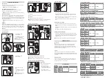
Measuring AC Amps
• Press SELECT to change
between AC/DC
• Press RANGE to select range
prior to using MAX/MIN.
NOTE:
Max capture is useful for
motor inrush current.
Measuring AC/DC Volts
• Press SELECT to change
between AC/DC
Measuring Frequency or Duty Cycle
• Must be AC Volt or AC µA
mode
• Press HZ/DUTY to select and
change between frequency or
duty cycle
NOTE:
Frequency greater than
1MHz will display 0.000
Measuring Resistance and Capacitance
Warning
DO NOT measure resistance on a live circuit.
Warning
Safely discharge capacitor before measurement.
NOTE:
Leave meter connected to the capacitor for 10 seconds allowing the
reading to settle. Larger capacitors could take up to 60 seconds.
Measuring Continuity and Diode
Press SELECT to change between continuity and diode
NOTE:
Continuity tone sounds at approximately <50Ω.
NOTE:
Shows voltage drop if forward biased and O.L. if reversed biased.
Measuring Temperature (DL379B and DL389 only)
Warning
Disconnect test lead probes from
voltage source and meter.
• Slide temperature input
jack lock switch down prior to
connecting temperature probe.
• Press SELECT to change
between Fahrenheit or Celsius.
Temperature Calibration
• Connect temperature probe as directed above.
• Remove battery cover. Place temperature probe in a known standard
temperature. Stirred crush ice in distilled water can be used for 32°F.
• Adjustments are made by accessing the potentiometer through the lower
right access port in the battery compartment.
• Using a fine tip standard screwdriver, adjust the potentiometer to 32°F
(0°C).
Measuring Non-Contact Voltage
• Press and hold the NCV button and move the sensor tip on the clamp
head near the voltage source. Both a visual and audible alert will indicate
voltage.
• The DL379B Hi/Lo NCV indicates LOW voltage at <120V and HIGH voltage
at >120V.
• NOTE: The worklight will be disabled during NCV tests.
Attaching / Detaching Clamp Heads
• To detach the clamp head first unplug all test leads and probes. Firmly
grab clamp head and base and pull apart. When attaching a clamp head
or attachment, align heads and push together ensuring the heads lock
together securely.
NOTE:
Leaving clamp head or attachment plugged in will drain battery.
PERIODIC SERVICE
Warning
Repair and service of this instrument is to be performed by qualified
personnel only. Improper repair or service could result in physical
degradation of the meter, altering the protection from electrical shock
and personal injury this meter provides to the operator. Perform only the
maintenance task you are qualified to do.
Cleaning
Periodically clean your meter’s case using a damp cloth. DO NOT use
abrasive, flammable liquids, cleaning solvents or strong detergents as they
may damage the finish, impair safety or affect the reliability of the structural
components.
Battery Replacement
Remove screws from battery compartment cover on back of meter and
remove cover. Replace batteries with fresh batteries paying attention to
polarity position. Replace cover and screws.
SPECIFICATIONS
DC Volts
Range
Resolution
Accuracy
Overload Protection
400mV
0.1mV
±(0.5% + 4 dgts)
1000V RMS
4V
1mV
40V
10mV
400V
100mV
1000V
1V
±
(
0.8% + 10
dgts)
AC Volts (45Hz to 400Hz)
Range
Resolution
Accuracy
Overload Protection
400mV
0.1mV
±(2.0% +5 dgts)
750V RMS
4V
1mV
40V
10mV
400V
100mV
750V
1V
AC Amps Measurement - Jaw Input (45~400Hz)
Range
Resolution
Accuracy
Overload Protection
40A
0.01A
±(2.9% + 15 dgts)
400A
400A
0.1A
±(1.9% + 8 dgts)
DL369: 400A range only
DL389: 45Hz to 400Hz True RMS (Crest factor<3:1)
DC Low Amps Measurement (Test Lead Input)
Range
Resolution
Accuracy
Overload Protection
400µA
0.01µA
±(1.2% + 3 dgts)
2000µA/600V RMS
2000µA
0.1µA
AC Low Amps Measurement (Test Lead Input 45Hz to 400Hz)
Range
Resolution
Accuracy
Overload Protection
400µA
0.01µA
±(2.0% + 5 dgts)
2000µA/600V RMS
2000µA
0.1µA
±(1.5% + 5 dgts)
DL389: 45Hz to 400Hz True RMS (Crest factor<3:1)
Resistance
Range
Resolution
Accuracy
Overload Protection
400Ω
100mΩ
±(1.0% + 4 dgts)
600V RMS
4kΩ
1Ω
40k
Ω
10
Ω
400k
Ω
100
Ω
4M
Ω
1k
Ω
40M
Ω
10k
Ω
±(2.0% + 4 dgts)
Capacitance Measurement
Range
Resolution
Accuracy
Overload Protection
40nF
0.01nF
±(3.5% + 6 dgts)
600V RMS
400nF
0.1nF
4µF
0.001µF
40µF
0.01µF
400µF
0.1µF
4000µF
1µF
DL379B: Capacitance range to 2000µF
Diode Test
Range
Open Circuit V
Test Current
Overload
2.0V
<1.6V DC
0.25mA
600V RMS
Frequency Measurement
Range
Resolution
Accuracy
Overload Protection
9.999Hz
0.001Hz
±(0.1% + 4 dgts) 600V RMS
99.99Hz
0.01Hz
999.9Hz
0.1Hz
9.999kHz
1Hz
99.99kHz
10Hz
199.9kHz
100Hz
Minimum Frequency: 0.5Hz, DC V offset should be zero
Sensitivity: >10% of each AC Volt range except 4V (>20%) range only
Temperature Measurement
Range
Resolution Accuracy
Overload Protection
-22˚ ~ 14˚F
0.1˚F
±(1.0% +5.4˚F)
30V RMS
15˚ ~ 752˚F
±(1.0% + 3.6˚F)
(-30˚ ~ -10˚C)
(0.1˚C)
(1.0% +3.0˚C)
(-9˚ ~ 400˚C)
(±1.0% + 2.0˚C)
Duty (%) Cycle Measurement
Range
Accuracy
Overload
Protection
01. to 99.9% ±(0.2% per kHz +0.1%) + 5 counts
600V RMS
0.5Hz to 100kHz (pulse width >2µsec)
Continuity Measurement
FIL CONDUCTEUR NOIR
FIL CONDUCTEUR ROUGE
FIL CONDUCTEUR ROUGE
FIL CONDUCTEUR NOIR
WIRE CURRENT
LINE SPLITTER


