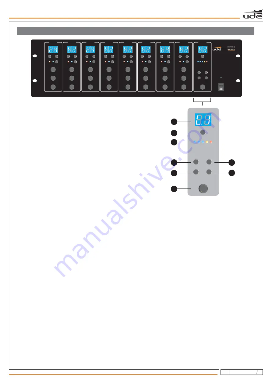
background image

H. LED display

I. System monitoring

J. Monitor VU meter

K. Monitor volume

L. Enter button

M. General broadcasting (BGM ALL)

N. ESC button

O. General paging (PAGE ALL)

A dual digit display shows the audio source selection for the monitor.

The MX-800 includes an internal speaker that enables the monitoring of the different matrix's outputs locally. By pressing
the “ZONE SELECT” button the user will be able to choose within the 8 possible outputs as well as disable it. Once the
output has been selected, the user must press the ENTER button. Otherwise the system will return to its original status.

5 LED meter shows the audio signal level of the selected zone.

Monitor control audio volume knob.

When the systems needs to be confirmed, the “ENTER” button should be pressed.

By selecting this option (BGM ALL), the system will assign a chosen audio input to all outputs automatically. To be able to
select the specific input, the user must press the BGM ALL button until the display shows the desired audio input. Then,
press “ENTER” to confirm.

The "ESC" button cancels all selection and operation not yet confirmed.

By selecting this option (PAGE ALL), the system will assign the MIC1's highest priority to all outputs automatically. To
monitor this selection, the MIC1 LED located on each input will be switched on.

MX-800 FRONT PANEL

MX-800

ZONE SELECT

OUTPUT LEVEL

FUNCTION

ENTER

BGM ALL

PAGE ALL

EMERGENCY

ESC

MONITOR

2

3

4

5

0

1

6

7

8

10

9

H

I

J

L

N

M

K

O

5

ZONE 1

ZONE 8

ZONE 2

ZONE 3

ZONE 4

ZONE 5

ZONE 6

ZONE 7

MONITOR

12

3

610.387A

rev.

2

Summary of Contents for MX-800

Page 1: ... dB 10 10 dB 3 dB OUTPUT DISABLE ENABLE REMOTE SOURCE 1 0V 1 2 300mV 1 1V 10KΩ dB dB GAIN REMOTE WALL CONTROL HF LF 0V 1 3 2 PAGE GAIN 10 10 dB 10 10 dB 3 dB OUTPUT DISABLE ENABLE REMOTE SOURCE 1 0V 1 2 300mV 1 1V 10KΩ dB dB GAIN REMOTE WALL CONTROL HF LF 0V 1 3 2 PAGE GAIN 10 10 dB 10 10 dB 3 dB OUTPUT DISABLE ENABLE REMOTE SOURCE 1 0V 1 2 1 5V 600Ω 1 5V 600Ω 1 5V 600Ω 1 5V 600Ω 1 5V 600Ω 1 5V 60...

Page 2: ...any other input Every paging zone audio output has an individual MIC 1 volume control The music volume control for each paging zone If the MX 800 audio matrix has a remote control MX 888 connected the music volume control will not work The master volume control enables the output gain adjustment for each zone of the MX 800 matrix If the priority of this zone is activated this control will not be a...

Page 3: ...ntrol audio volume knob When the systems needs to be confirmed the ENTER button should be pressed By selecting this option BGM ALL the system will assign a chosen audio input to all outputs automatically To be able to select the specific input the user must press the BGM ALL button until the display shows the desired audio input Then press ENTER to confirm The ESC button cancels all selection and ...

Page 4: ... MIC 5mV LINE 350mV MIC 5mV LINE 350mV MIC 5mV LINE 350mV dB GAIN GAIN dB LINE 1 LINE 2 R L R L dB GAIN R L 195mV 2V 47KΩ 1 2 A A1 A1 A1 A1 B B B B A A A B1 B1 B1 B1 LINE INPUT 1 LINE INPUT 2 LINE INPUT 3 LINE INPUT 4 LINE INPUT 5 LINE INPUT 6 LINE INPUT 7 LINE INPUT 8 CONFIGURABLE BALANCED LINE INPUTS BALANCED LINE INPUTS MIC MIC MIC MIC PHANTOM PHANTOM PHANTOM PHANTOM LINE LINE LINE LINE G G G G...

Page 5: ... for each one Besides the paging desk MX 801 itself includes its own adjustments on the rear part as follows 1 2 3 4 5 6 Power switch Supply input RJ45 port Microphone volume control Chime volume control Chime selector 2 or 4 tones and OFF position 0 10 MIC VOL 0 10 CHIME VOL ON OFF COM CHIME POWER 24VDC 4 TONE 2 TONE OFF SERIAL NO PUBLIC ADDRESS SYSTEM MX 101 1 2 3 4 5 6 3 MX 801 1 PAGING DESK CO...

Page 6: ... 5 5 0 0 0 1 1 1 6 6 6 7 7 7 8 8 8 10 10 10 9 9 9 SOURCE UP SOURCE DOWN PAGE BUSY MIC1 PRIORITY D 4 3 MIC1 Priority Each of the 8 matrix outputs MX 800 includes a priority button on the front panel that enables the MIC1 input to have highest priority against any input signals of a specific zone This selection is independent for each output and once it is enabled the MIC1 LED will be switched on In...

Page 7: ...signal and will broadcast it to all 8 zones Next we show possible solutions with UDE equipment The first one consists of a GD 36 pre recorded message player connected that can be integrated with the fire alarm system as well The second option consist of a preamplifier that can actually mix the input of a GD 36 as well as a microphone input and a music source as well This way any of these audio sou...

Page 8: ...ystem the user should use the DIP switch by selecting any of the following combinations master slave 1 slave 2 slave 3 If the selection of the combinations is configured incorrectly it may lead to the malfunctioning of the system When connecting any of the Slave matrix only the master matrix inputs 8 audio inputs MIC1 and paging desk will be operative All the slave matrix inputs will be disabled T...

Page 9: ...is connected This adjustment is used to control the remote source s gain This will provide an independent adjustment for each zone Each zone can have a level remote source assigned to it It is designed like this in order to enable users who do not want to use the local line input of the remote panels to have the possibility of choosing a remote source for only that zone Once the MX 888 is linked w...

Page 10: ... connector MIC1 on the rear part of the device Only one microphone can be used even if there is more than one matrix interconnected This microphone allows the system to provide a configurable priority input The MX 800 matrix allows the connection of up to 8 outputs In case of an expanded matrix system the possible outputs increase up to 32 The audio output is connected using a terminal black label...

Page 11: ...s follows The different interconnected matrix must be correctly identified by using the switch DIP ON Any of the 4 combinations must be selected to identify if it as a MASTER matrix or any of the 3 SLAVE matrix available LINK OUT LINK OUT LINK OUT LINK IN LINK IN LINK IN MASTER MATRIX SLAVE MATRIX 1 SLAVE MATRIX 2 SLAVE MATRIX 3 SYSTEM CONFIGURATION MX 800 MX 800 1 MX 800 2 MX 800 3 MX 800 4 12 11...

Page 12: ...sabled from the matrix It must be done from the remote control panel itself 6 AUDIO EQUALIZATION 1 2 3 4 5 The MX 800 matrix provides several gain adjustments for audio inputs and outputs Therefore the following steps must be verified Adjust the gain control of every line input Adjust the gain control of all paging desks MX 801 from their rear panel as well as from the matrix s rear panel Adjust g...

Reviews: