ODIN-W2 series - System integration manual
UBX-14040040 - R20
System description
Page 8 of 43
C1-Public
1.1.1
Module architecture
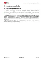
Figure 1: Block diagram of ODIN-W2 series
1.1.2
Radio interfaces
The radio frequency (RF) section contains an RF transceiver, RF switches, RF filters, RF diplexer and
a high tolerance crystal oscillator. The transceiver has the following five RF ports:
•
Bluetooth 2.4 GHz in/out, Classic Bluetooth and Bluetooth low energy
•
Wi-Fi 2.4 GHz band main port in/out
•
Wi-Fi 5 GHz band In
•
Wi-Fi 5 GHz band out
•
Wi-Fi 2.4 GHz band MIMO port in/out
The Wi-Fi MIMO port is separate from the other ports and connected directly to a coaxial U.FL.
connector through a band pass filter. The U.FL. connector should be connected to an external antenna
through a coaxial cable. See Approved antennas section in
ODIN-W2 series Data sheet [2] section for
more information about how to select the antennas.
☞
The MIMO port/functionality is available only in the ODIN-W260 module.
Different antenna options are available depending on the chosen ODIN-W2 series model:
•
ODIN-W260: A standard coaxial U.FL. connector that must be connected to an external antenna
through a coaxial cable. See Antenna connectors section for more information about the antenna
connectors.
•
ODIN-W262 and ODIN-W263: An internal dual-band PIFA antenna. See Internal antenna
subsection for more information about the internal antenna. ODIN-W263 is a special version of
ODIN-W262 configured to always support the ETSI domain and is only allowed to be used in
countries allowing ETSI domain channels.
Three internal DC/DC regulators generate 1.1 V, 1.8 V and 2.7 V to the RF parts.
1.1.3
Host processor
The host processor is composed of a high-performance Arm
®
Cortex
®
-M4 with FPU. The MCU
operates at a system frequency of up to 168 MHz and has 2 MB of Flash and 256 KB of RAM memory.
A 24 MHz crystal supplies the host for accurate interface timing. The host enables communication
with the ODIN-W2 module over both UART and RMII.


